Introduction
LED matrices are versatile display components that can be used for a wide range of applications, from simple signage to interactive notification systems. In this blog post, I'll walk you through the process of building a 3x5 LED matrix controlled by a Raspberry Pi Pico using tscircuit, a powerful circuit design tool that uses code to create electronic circuits.
What is tscircuit?
tscircuit is a modern circuit design tool that allows you to create electronic circuits using code. It provides a component-based approach to PCB design, making it easier to create, modify, and share circuit designs programmatically.
Objective of Building an LED Matrix
Before diving into technical details, let's understand why you might want to build an LED matrix.
- Signage - Building signs for events, products, etc.
- Data Visualization Tool - Displaying real-time data metrics like GitHub contributions, website traffic, or temperature reading through color intensity.
- Interactive Notification System - Creating a physical notification system for emails, social media, or calendar events with customizable brightness levels.
LED Matrix Requirements
For this project, our LED matrix needs to meet the following requirements:
- WiFi-controllable
- Grid-based layout pattern
- Each LED should be individually controllable for brightness and color
System Architecture
How the components connect together? 🤔
The matrix connects to the Pico microcontroller via a data chain. The Pico connects to WiFi through the PICO_W module. This creates a complete system where:
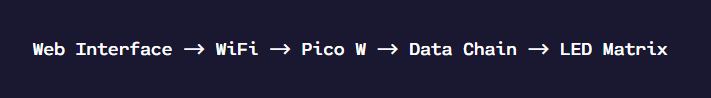
Key Components
- Raspberry Pi Pico W - Microcontroller with WiFi capabilities
- WS2812B - IC LEDs with integrated control chip
- Web Interface - For controlling the LED matrix remotely
LED Schematic
For this project, we're using IC LEDs (specifically WS2812B), which have an RGB LED and control chip integrated into the same package. These IC LEDs offer several advantages over traditional RGB LEDs:
- Simplified Wiring - Only 4 pins are needed (VDD, GND, Data In, Data Out) compared to 4+ pins for traditional RGB LEDs
- Serial Communication - LEDs can be daisy-chained together, requiring only one data pin from the microcontroller
- Individual Control - Each LED in the chain can be controlled independently for color and brightness.
Building the Circuit with tscircuit
One of the most powerful aspects of tscircuit is its component-based approach to circuit design. Let's look at how we can chain two LEDs together:
import { WS2812B_2020 as LedWithIc } from "@tsci/seveibar.WS2812B_2020";

export default () => (
    <board>
        {/* First LED */}
        <LedWithIc
            schX={0}
            schY={0}
            name={"LED1"}
        />
        {/* Secomd LED */}
        <LedWithIc
            schX={5}
            schY={0}
            name={"LED2"}
        />

        {/* Connecting the LEDs to GND and VDD */}
        <trace from={".LED1 .GND"} to="net.GND" />
        <trace from={".LED2 .VDD"} to="net.V5" />

        <trace from={".LED2 .GND"} to="net.GND" />
        <trace from={".LED2 .VDD"} to="net.V5" />

        {/* Connecting the LEDs together */}
        <trace from={".LED1 .DO"} to={".LED2 .DI"} />
    board>
)
This code creates two WS2812B LEDs and connects them together by linking the data output (DO) of the first LED to the data input (DI) of the second LED. It also connects both LEDs to the ground and the 5V power supply.
Creating the LED Matrix
To create a 3x5 LED matrix, we could manually place and connect 15 LEDs, but that would be tedious. Instead, tscircuit provides a helper function called grid that makes it easy to create a grid of components:
import { WS2812B_2020 as LedWithIc } from "@tsci/seveibar.WS2812B_2020"
import { grid } from "@tscircuit/math-utils"

export default () => {
    return (
        <board width="65mm" height="52mm" routingDisabled>
            {/* 3x5 LED matrix */}
            {grid({ cols: 3, rows: 5, xSpacing: 8, ySpacing: 5, offsetX: 20, offsetY: 5 }).map(
                ({ center, index }) => {
                    const ledName = "LED" + (index + 1)
                    const prevLedName = index > 0 ? "LED" + (index) : null
                    return (
                        <>
                            {/* LED */}
                            <LedWithIc schX={center.x / 2} schY={5 + center.y / 2} name={ledName} />

                            {/* Connecting the LED to GND and VDD */}
                            <trace from={".LED" + (index + 1) + " .GND"} to="net.GND" />
                            <trace from={".LED" + (index + 1) + " .VDD"} to="net.V5" />

                            {/* Connecting the LED to the previous LED */}
                            {prevLedName && <trace from={".LED" + (index) + " .DO"} to={".LED" + (index + 1) + " .DI"} />}
                        >
                    )
                }
            )}
        board>
    )
}
This code creates a 3x5 grid of LEDs with proper spacing and automatically connects them in a chain. Each LED is given a unique name (LED1, LED2, etc.) and is connected to the ground and the 5V power supply.
Connecting the Pico to the LED Matrix
Now that we have our LED matrix, we need to connect it to the Raspberry Pi Pico. We'll use the GP6 pin on the Pico to control the LED matrix:
import { usePICO_W } from "@tsci/seveibar.PICO_W"
import { WS2812B_2020 as LedWithIc } from "@tsci/seveibar.WS2812B_2020"
import { grid } from "@tscircuit/math-utils"

export default () => {
    const U1 = usePICO_W("U1")
    return (
        <board width="60mm" height="60mm" routingDisabled>
            {/* Pico microcontroller */}
            <U1 />

            {/* LED matrix */}
            {grid({ cols: 3, rows: 5, xSpacing: 8, ySpacing: 5, offsetX: 20 }).map(
                ({ center, index }) => {
                    const ledName = "LED" + (index + 1)
                    const prevLedName = index > 0 ? "LED" + (index) : null
                    return (
                        <>
                            {/* LED */}
                            <LedWithIc schX={center.x / 2} schY={5 + center.y / 2} name={ledName} />

                            {/* Connecting the LED to GND and VDD */}
                            <trace from={".LED" + (index + 1) + " .GND"} to="net.GND" />
                            <trace from={".LED" + (index + 1) + " .VDD"} to="net.V5" />

                            {/* Connecting the LED to the previous LED */}
                            {prevLedName && <trace from={".LED" + (index) + " .DO"} to={".LED" + (index + 1) + " .DI"} />}
                        >
                    )
                }
            )}

            {/* Connecting the Pico to the LED matrix using GP6 pin */}
            <trace from={U1.GP6_SPI0SCK_I2C1SDA} to={".LED1 .DI"} />

            {/* Connecting the Pico to GND */}
            <trace from={U1.GND1} to="net.GND" />
            <trace from={U1.GND2} to="net.GND" />
            <trace from={U1.GND3} to="net.GND" />
            <trace from={U1.GND4} to="net.GND" />
            <trace from={U1.GND5} to="net.GND" />
            <trace from={U1.GND6} to="net.GND" />
            <trace from={U1.GND7} to="net.GND" />
        board>
    )
}
This code imports the Pico W component, creates our LED matrix, and connects the GP6 pin of the Pico to the data input of the first LED in the chain. It also connects all the ground pins of the Pico to the ground net.
PCB Layout
With our schematic complete, we can now create a PCB layout. In tscircuit, we can specify the physical positions of components on the board:
import { usePICO_W } from "@tsci/seveibar.PICO_W"
import { WS2812B_2020 as LedWithIc } from "@tsci/seveibar.WS2812B_2020"
import { grid } from "@tscircuit/math-utils"

export default () => {
    const U1 = usePICO_W("U1")
    return (
        <board width="65mm" height="60mm" routingDisabled>
            {/* Pico microcontroller */}
            <U1 pcbRotation="90deg" pcbX={-15} pcbY={0} />

            {/* LED matrix */}
            {grid({ cols: 3, rows: 5, xSpacing: 8, ySpacing: 5, offsetX: 20, offsetY: 5 }).map(
                ({ center, index }) => {
                    const ledName = "LED" + (index + 1)
                    const prevLedName = index > 0 ? "LED" + (index) : null
                    return (
                        <>
                            {/* LED */}
                            <LedWithIc schX={center.x / 2} schY={5 + center.y / 2} name={ledName} pcbX={center.x} pcbY={center.y} />

                            {/* Connecting the LED to GND and VDD */}
                            <trace from={".LED" + (index + 1) + " .GND"} to="net.GND" />
                            <trace from={".LED" + (index + 1) + " .VDD"} to="net.V5" />

                            {/* Connecting the LED to the previous LED */}
                            {prevLedName && <trace from={".LED" + (index) + " .DO"} to={".LED" + (index + 1) + " .DI"} />}
                        >
                    )
                }
            )}

            {/* Connecting the Pico to the LED matrix using GP6 pin */}
            <trace from={U1.GP6_SPI0SCK_I2C1SDA} to={".LED1 .DI"} />

            {/* Connecting the Pico to GND */}
            <trace from={U1.GND1} to="net.GND" />
            <trace from={U1.GND2} to="net.GND" />
            <trace from={U1.GND3} to="net.GND" />
            <trace from={U1.GND4} to="net.GND" />
            <trace from={U1.GND5} to="net.GND" />
            <trace from={U1.GND6} to="net.GND" />
            <trace from={U1.GND7} to="net.GND" />
        board>
    )
}
In this code, we've added physical positioning information for the components:
- The Pico is positioned at
pcbX=-15pcbY=0with a 90-degree rotation. - Each LED is positioned according to the grid function with proper spacing.
Controlling the LED Matrix
Once the hardware is built, we need a way to control the LED matrix. The tutorial describes a web interface that provides a visual grid for controlling individual LEDs:
Web Interface Features
Control System Includes:
-
Visual Grid Interface: A 3x5 grid where clicking each cell cycles through:
- Off (Gray)
- Red
- Green
- Blue
- API Integration: The matrix state can be controlled and monitored through REST endpoints, making it easy to integrate with other applications.
- Wireless Control: The matrix connects to WiFi using the Pico W's wireless capabilities, allowing for remote control through the web interface.
Ordering the PCB
Once your design is complete, you can order the PCB by downloading the fabrication files and uploading them to a PCB manufacturer like JLCPCB. The tutorial mentions that you can follow their instructions for ordering the PCB.
Conclusion
Building a 3x5 LED matrix with the tscircuit and a Raspberry Pi Pico is an excellent project that combines hardware design, programming, and web development. The component-based approach of the tscircuit makes it easy to create complex circuits with minimal code, and the Pico W's WiFi capabilities enable remote control of the LED matrix.
Whether you're building a simple signage system, a data visualization tool, or an interactive notification system, this project provides a solid foundation that you can build upon and customize to suit your needs.
Ready to Build Your Own?
Check out the full tutorial at docs.tscircuit.com