How to Design a Low Poly Tank Using 3D CAD Software
The art of low-poly modeling has become increasingly important in game design, animation, and 3D visualization, offering a balance between aesthetic appeal and performance optimization. SelfCAD, an intuitive and accessible 3D modeling software, provides the perfect platform for creating low-poly objects with precision and ease. This article will guide you through the process of designing a low-poly military tank, breaking down each step from basic shape formation to final detailing. Whether you're a beginner or an experienced 3D artist, mastering this technique in SelfCAD can help you create optimized, stylized models for various digital applications.
To access the interactive tutorial to this article, check out; https://www.selfcad.com/tutorials/10h6y252v1553y294j1644624b4c5l3j2xw1
Once you’ve launched the editor;
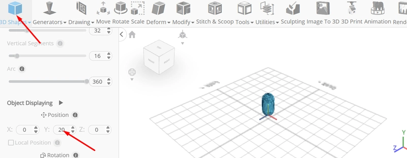
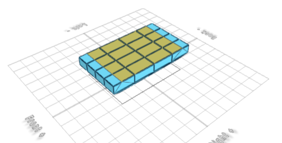
From the 3D Shapes category on the toolbar choose cube; Set width to 200, height to 70, depth to 350, width segment to 4, height segment to 2, depth segment to 4, position y to 30
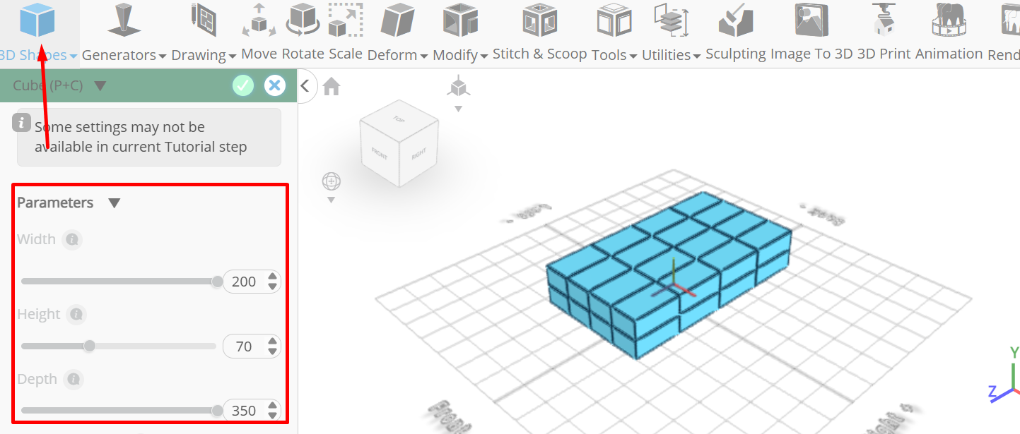
Tick the checkmark finalize cube
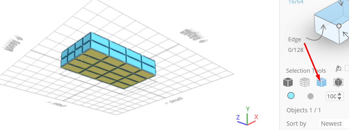
Click solid+wireframe button to set rendering mode; Click to activate polygon selection; Click on highlighted region to select it
Click scale on the toolbar; Set x to 151.87, z to 265.78 using highlighted gizmo
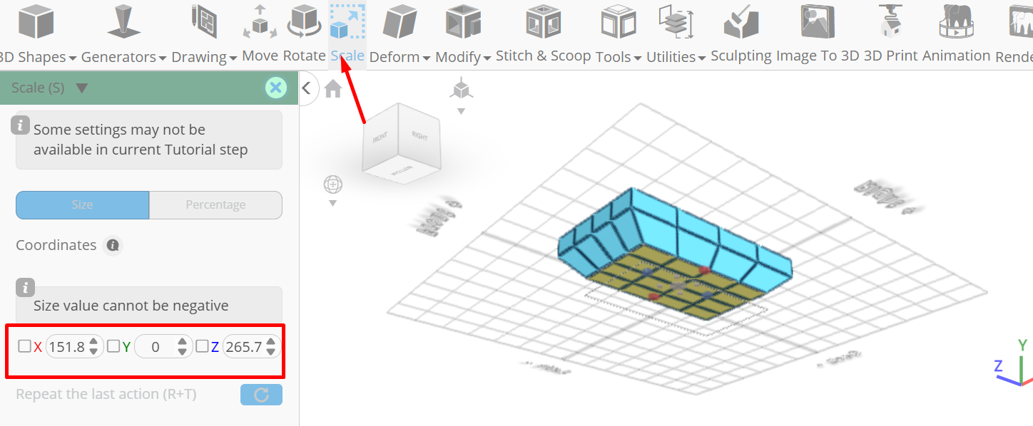
Click ‘x’ to close transformation panel
Click on highlighted region to deselect it
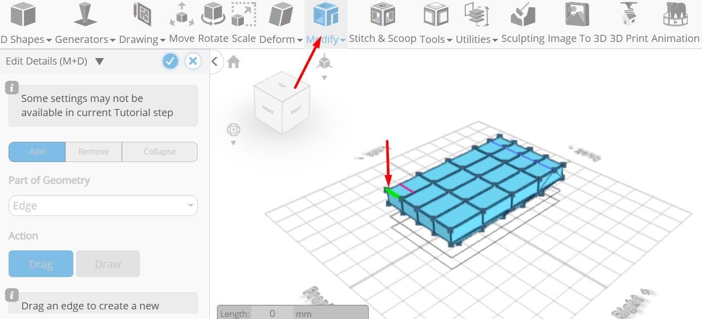
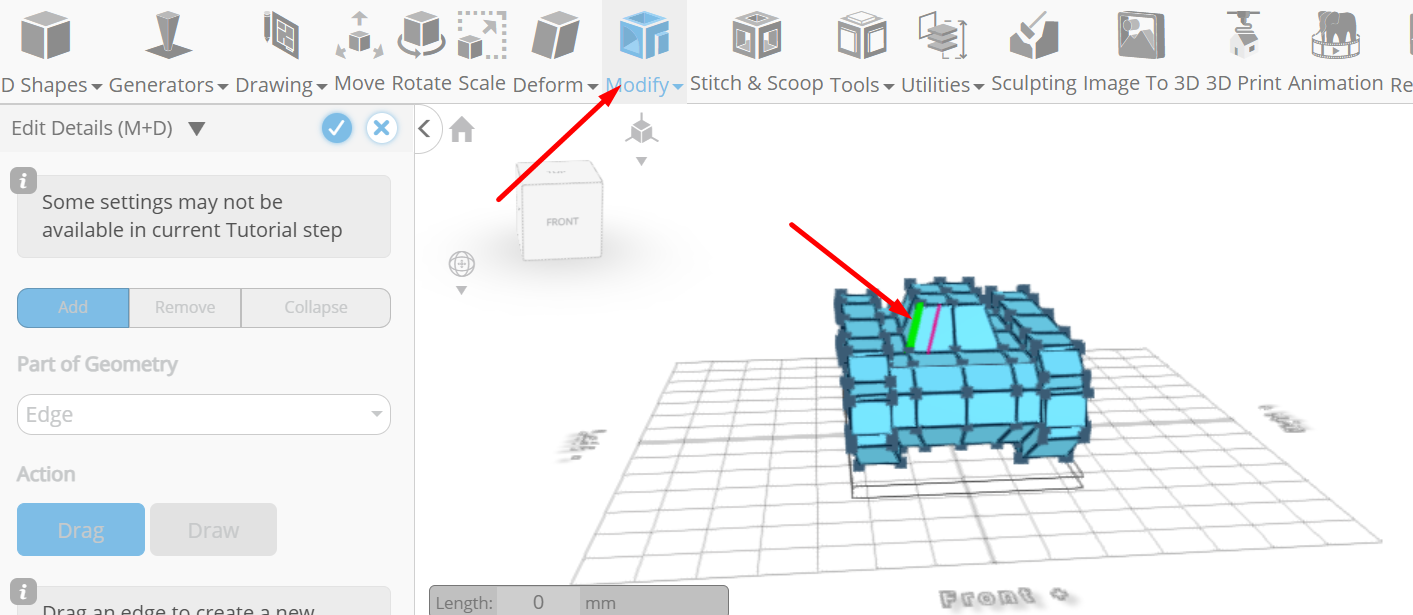
From the modify category on the toolbar choose edit details; Set loop finding to true, Drag highlighted edge to highlighted line to add edge loop
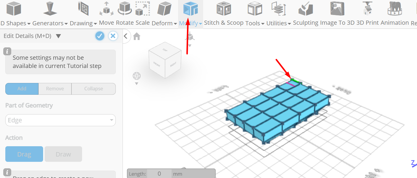
Drag highlighted edge to highlighted line to add edge loop
Tick the checkmark to finalize edit details
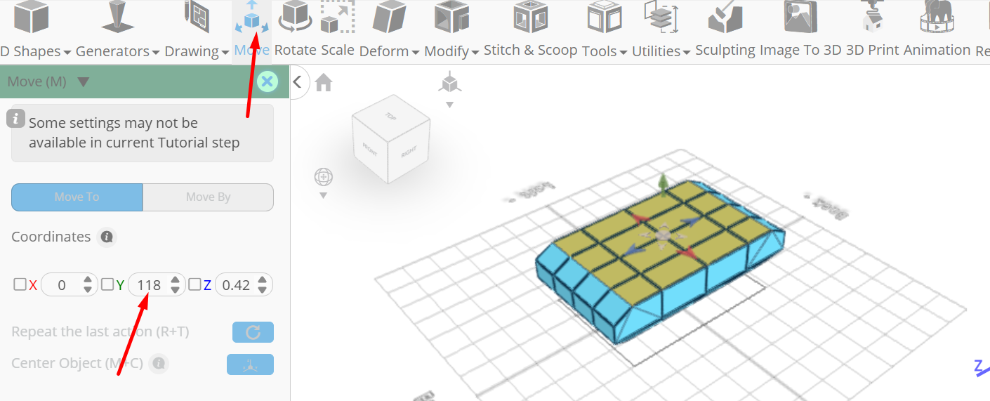
Click to activate face selection; Click on highlighted region to select it
Click move on the toolbar; Set y to 118 using highlighted gizmo
Click ‘x’ to close transformation panel
Click on highlighted region to deselect it
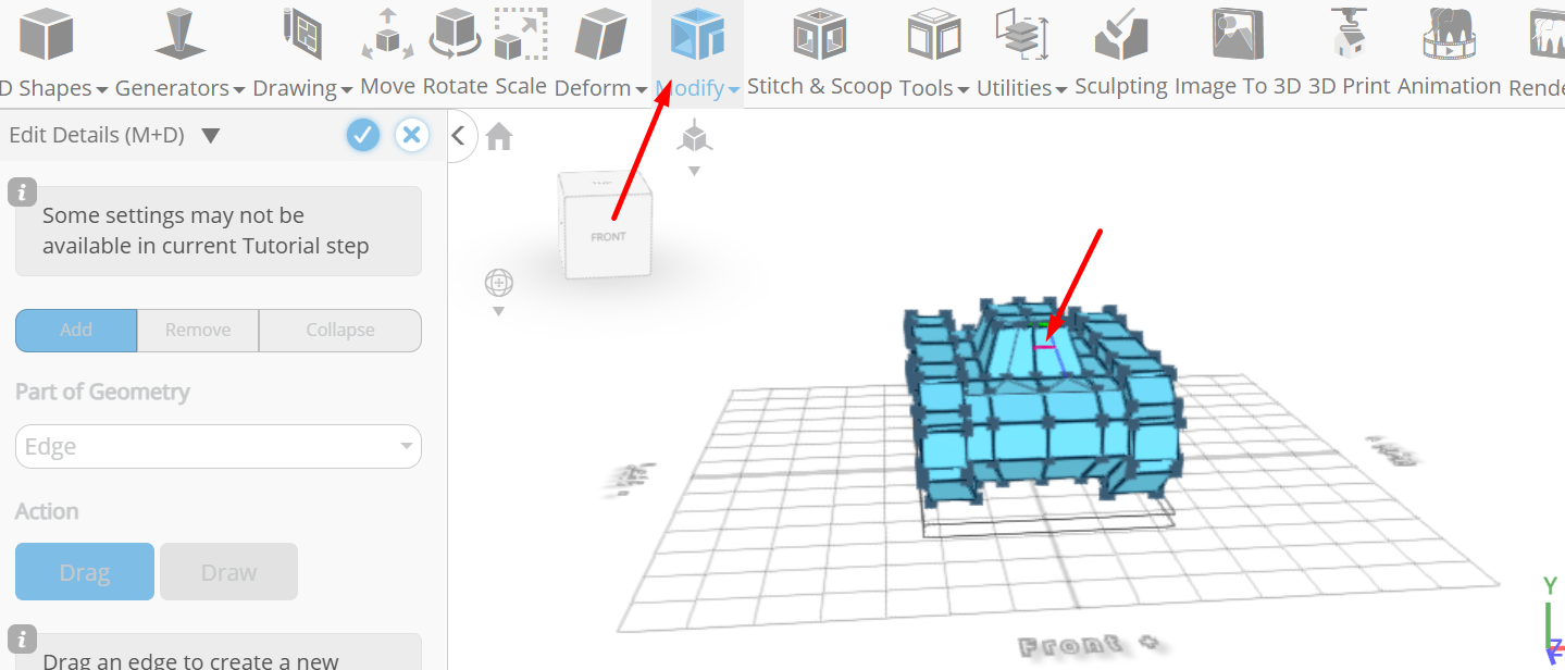
From the modify category on the toolbar choose edit details; Set loop finding to true, Drag highlighted edge to highlighted line to add edge loop
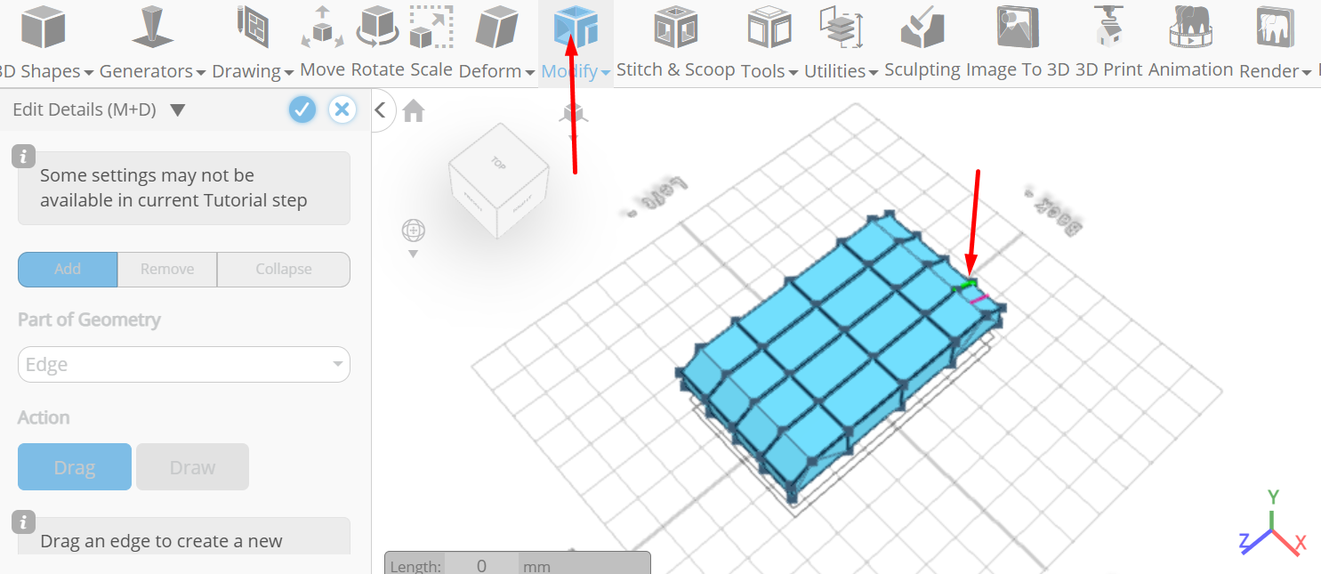
Drag highlighted edge to highlighted line to add edge loop
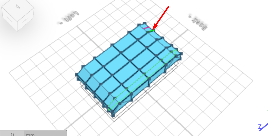
Tick the checkmark to finalize edit details
Click to activate polygon selection; Click on highlighted region to select it
Click move on the toolbar; Set x to -102.97 using highlighted gizmo
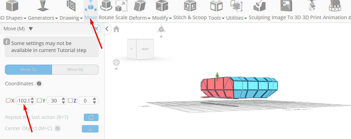
Click on highlighted region to deselect it
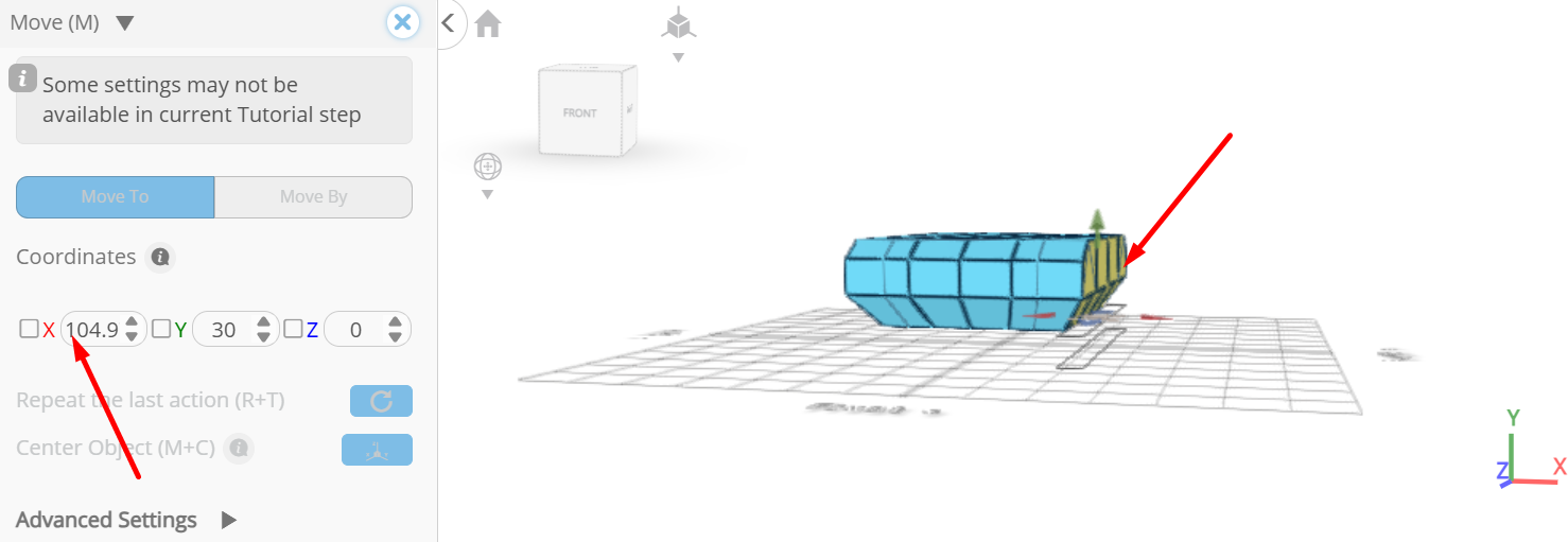
Click on highlighted region to select it; Set x to 104.97 using highlighted gizmo
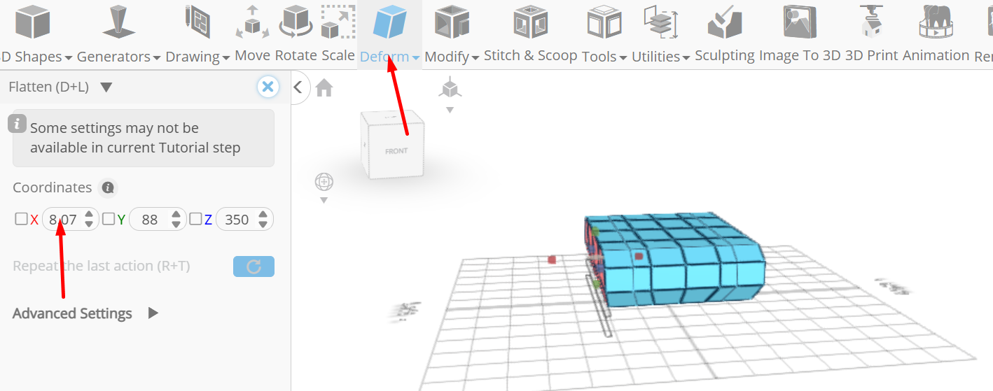
From the deform category on the toolbar choose flatten; Set x to 6.06 using highlighted gizmo
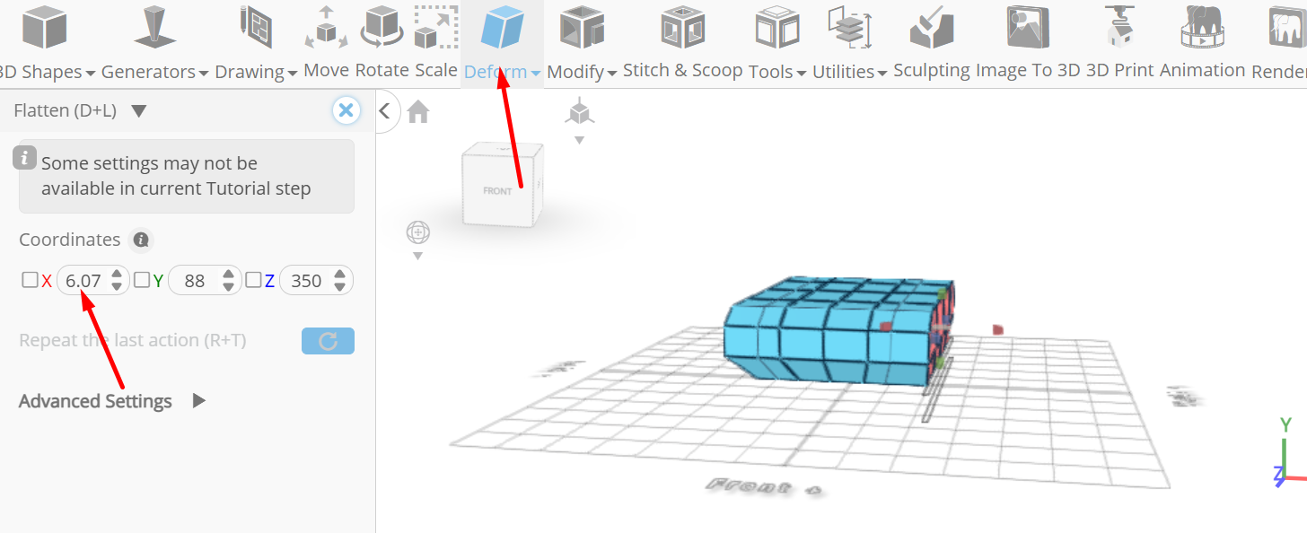
Click on highlighted region to deselect it
Click on highlighted region to select it; Set x to 8.06 using highlighted gizmo
Click on highlighted region to deselect it
Click to activate face selection;
Click on highlighted region to select it; From the modify category on the toolbar choose extrusion; Set is individual to true, extrusion amount to 17.6
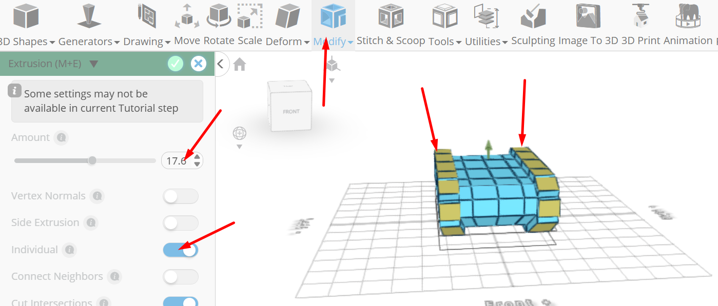
Tick the checkmark to finalize extrusion
Click on highlighted region to deselect it
Click on highlighted region to select it; From the modify category on the toolbar choose extrusion; Set extrusion amount to 45.13
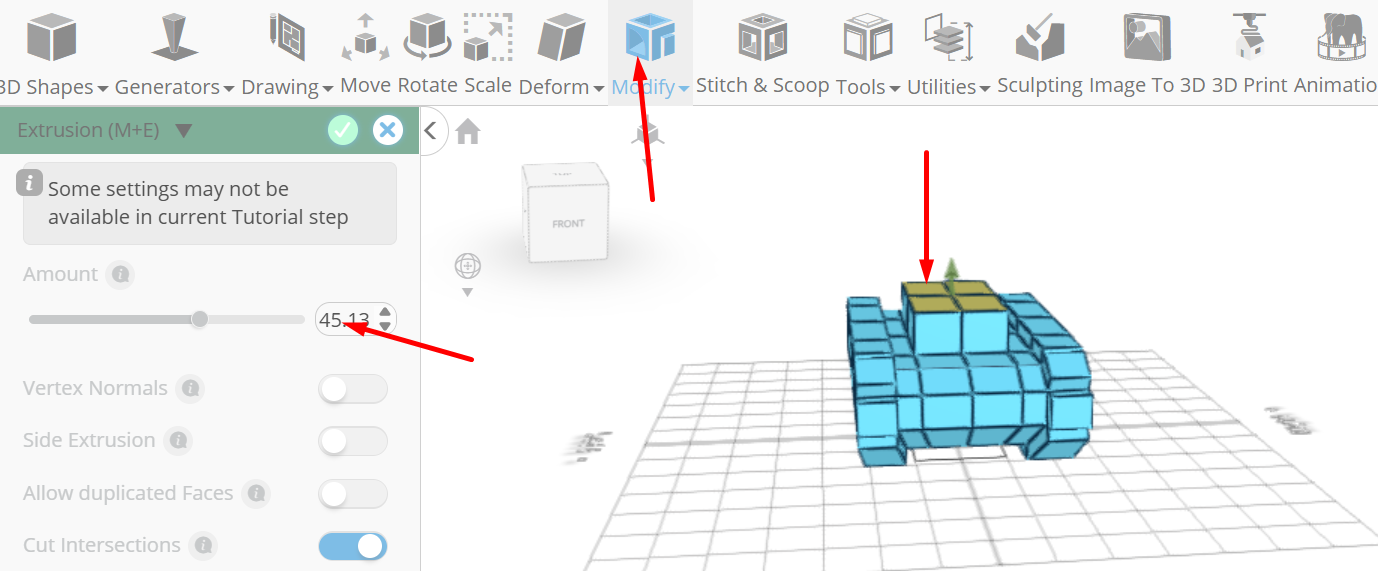
Tick the checkmark to finalize extrusion
Click scale on the toolbar; Set x to 69.24, z to 121.17 using highlighted gizmo
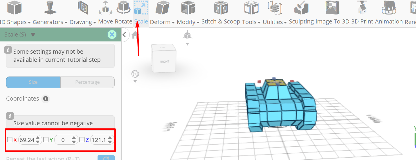
Click ‘x’ to close transformation panel
Click on highlighted region to deselect it
From the modify category on the toolbar choose edit details; Drag highlighted edge to highlighted line to add edge
Drag highlighted edge to highlighted line to add edge; Set loop finding to true, Drag highlighted edge to highlighted line to add edge loop
Tick the checkmark to finalize edit details
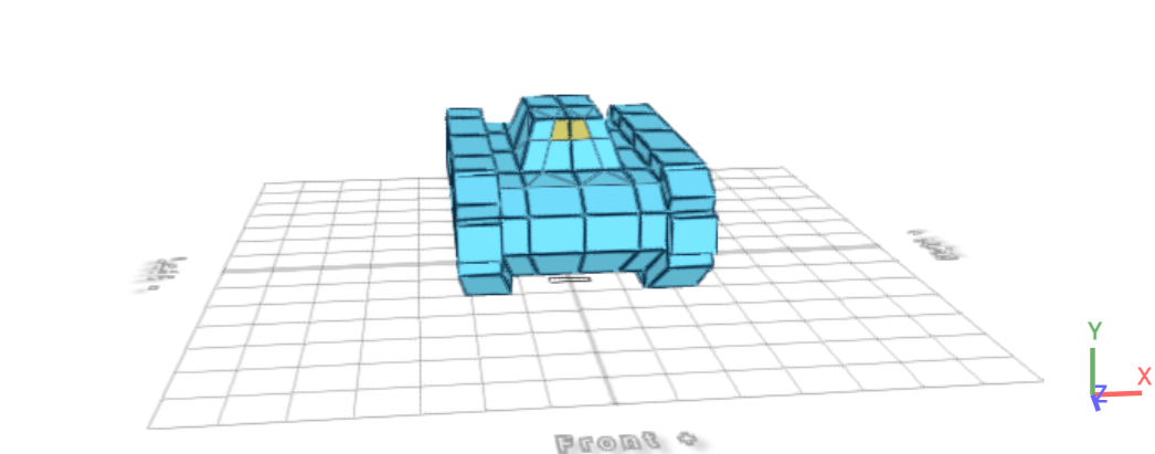
Click on highlighted region to select it
From the modify category on the toolbar choose extrusion; Set extrusion amount to 250
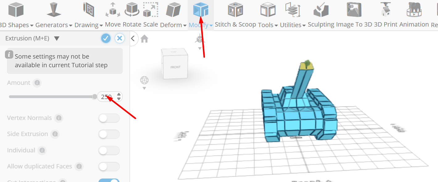
Click add option to add next macro step; Set operation to extrusion, amount to 20
Click add option to add next macro step; Set operation to extrusion, amount to 10
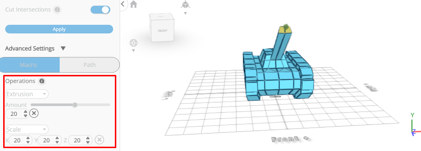
Tick the checkmark to finalize extrusion
Click delete button to delete selected objects
Click on highlighted region to select it; From the modify category on the toolbar choose extrusion; Set extrusion amount to 23.22
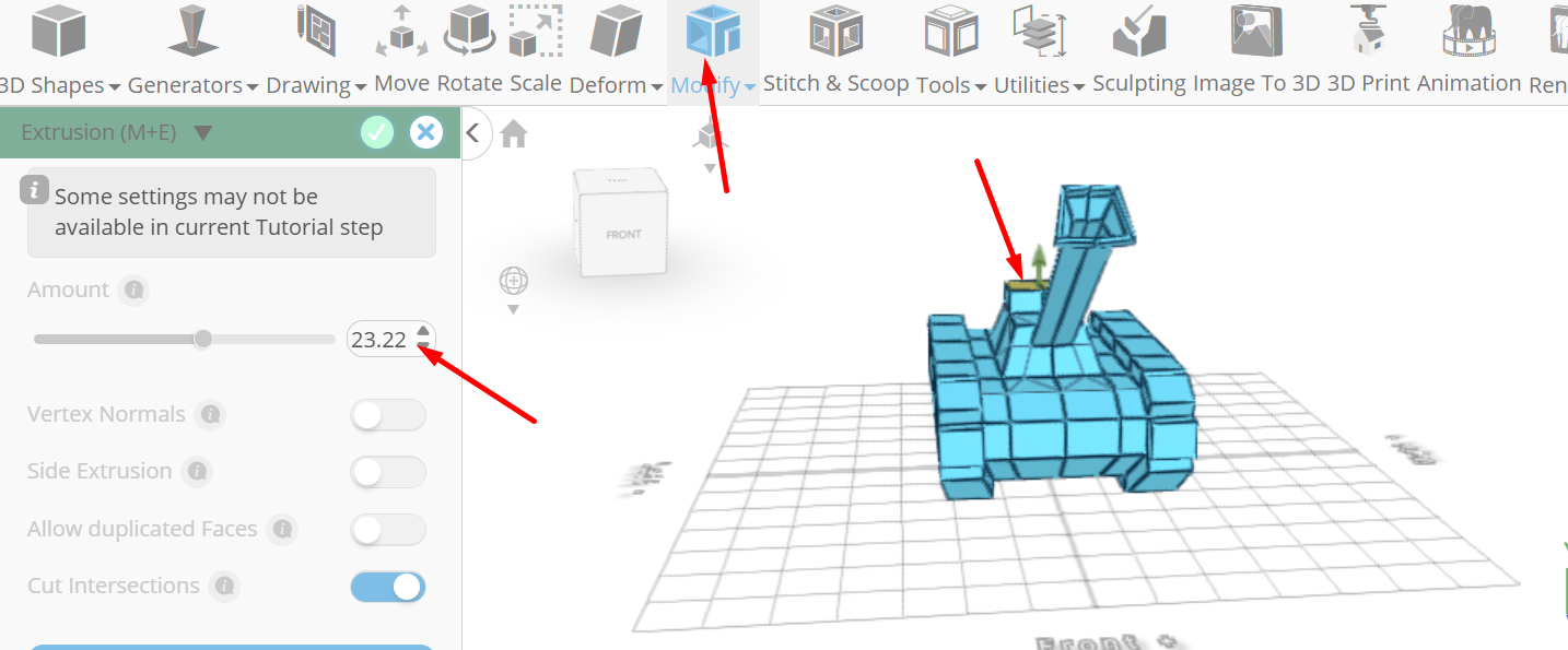
Tick the checkmark to finalize extrusion
Click scale on the toolbar; Set x to 46.66, z to 40.83 using highlighted gizmo
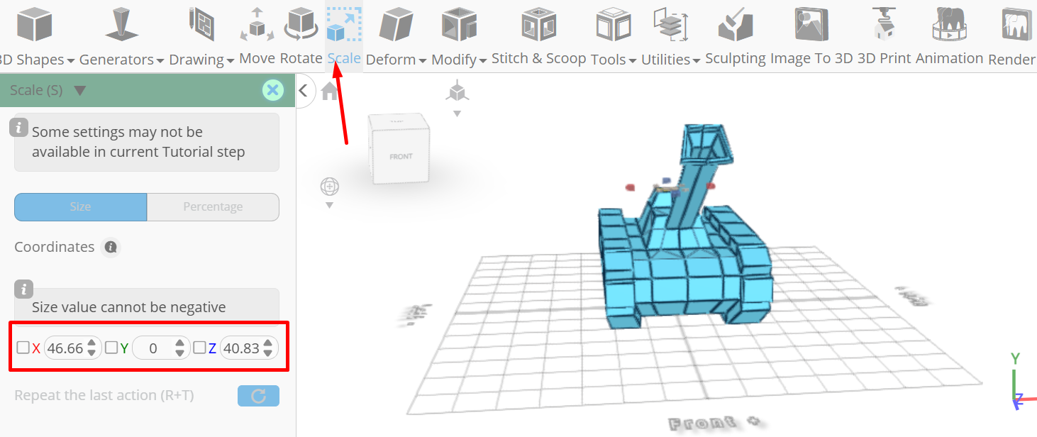
Click ‘x’ to close transformation panel
As you continue honing your design skills, remember that SelfCAD offers a wealth of resources to support your learning journey. To deepen your understanding and explore more advanced features, consider checking out the interactive tutorials (https://www.selfcad.com/tutorials) available on the SelfCAD website. The tutorials page provides a treasure trove of guides, tips, and tricks that cater to designers of all levels.
More structured learning experience can also be accessed at the SelfCAD Academy (https://www.selfcad.com/academy/curriculum/), https://www.youtube.com/@3dmodeling101, and 3D Modeling 101 series (https://www.youtube.com/playlist?list=PL74nFNT8yS9DcE1UlUUdiR1wFGv9DDfTB). This comprehensive resource offers in-depth courses taught by industry experts, allowing you to master the intricacies of SelfCAD at your own pace.