Water wastage due to tank overflow is a common issue faced in many homes and buildings. Fortunately, this problem can be effectively addressed with a simple and affordable solution: a Water Level Sensor. By integrating this sensor with an Arduino, we can monitor the water level inside a tank in real-time and trigger alerts—such as turning on an LED or buzzer—when the tank is about to overflow.
In this tutorial, you'll learn how water level sensors work, how to connect them to an Arduino.
How Does a Water Level Sensor Work?
A water level sensor detects the presence or height of water in a container by measuring the electrical resistance between exposed conductive traces. When water comes into contact with the sensor, it changes the resistance between these traces, which in turn alters the output voltage.
Here's how it works:
More water → more conductivity → lower resistance → higher output voltage
Less water → less conductivity → higher resistance → lower output voltage
This analog voltage output is then read by an Arduino analog pin and mapped to represent the water level. The deeper the water covers the sensor, the higher the voltage output.
Water Level Sensor Specifications
- Operating voltage: 3 to 5V, < 20mA
- Humidity: 10%-90% non-condensing
- Operating Temperature: 10℃-30℃
- Sensor Type: Analog
- Output Voltage Range: 0 to 3.85V
- Detection Area: 40mm (height) x 16mm (width)
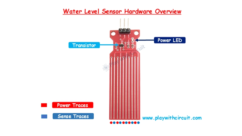
Water Level Sensor Hardware Overview
The water level sensor consists of 10 parallel conductive traces:
5 Power Traces (connected to VCC)
5 Sense Traces (connected to signal output)

These traces are arranged alternately so that each sensing trace is placed between two power traces. When water bridges the traces, it allows current to flow, which is interpreted by the internal circuit as an increase in water level.
The module also contains:
- A power LED to indicate the sensor is powered.
- An NPN transistor for switching behavior.
- Multiple resistors to limit current and protect the components.
Pinout of Water Level Sensor
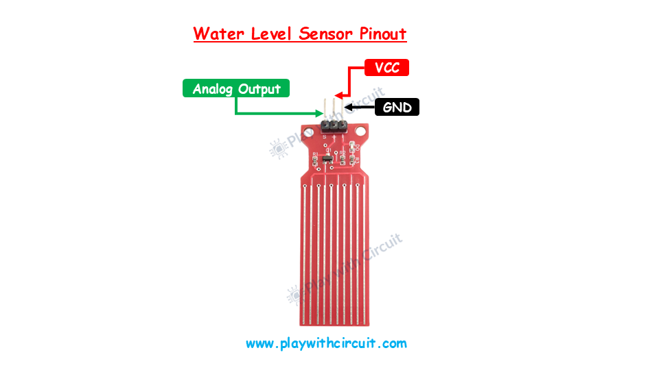
VCC: Power supply pin (connect to 5V on Arduino)
GND: Ground connection
OUT: Analog output (connect to Arduino analog pin)
Schematic Diagram
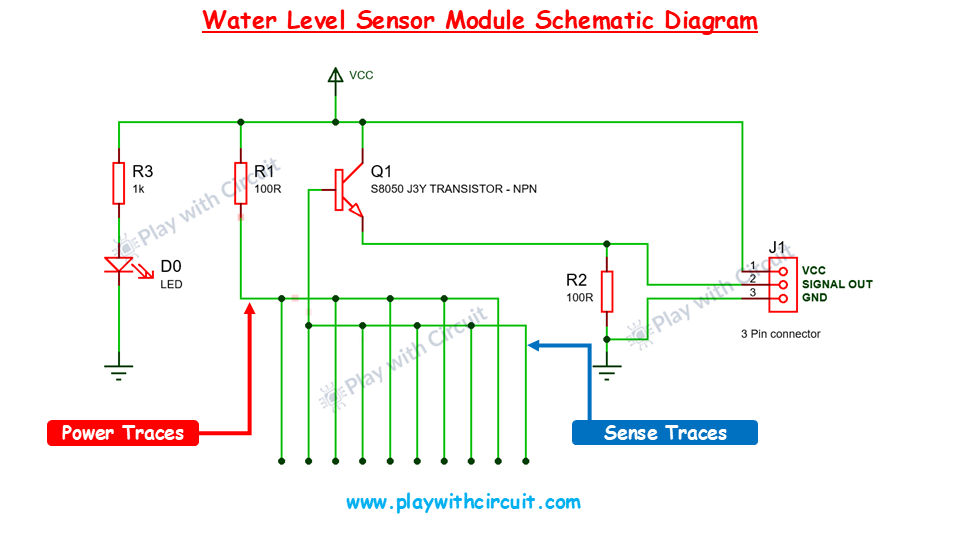
The internal working of the sensor module can be broken down into these parts:
NPN Transistor (Q1): Acts as a switch, turning on when the sensor detects water.
Resistors (R1, R2, R3): Limit the current and protect the components.
Copper Traces: The power traces are connected to VCC through resistors, and sense traces go to the transistor's base.
**Working Principle: **When water bridges the traces, it creates a voltage at the transistor’s base. This allows current to flow from collector to emitter, effectively turning the transistor ON. As a result, the signal pin provides an analog voltage output that increases with water level.
Wiring a Water Level Sensor to Arduino
The circuit diagram is shown as follows:
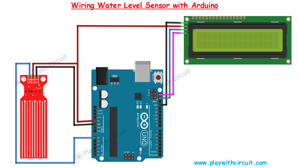
Wiring:
Sensor VCC → Arduino 5V
Sensor GND → Arduino GND
Sensor OUT → Arduino A0 (analog pin)
SCK and SDA pins of LCD → I2C pin of the Arduino
Arduino Code
/*
Interfacing Water Level Sensor with Arduino UNO using Analog Output pin of Module
by www.playwithcircuit.com
Using this code we will know the Analog Value when water level is very low and when it is very high.
*/
#include   // Library to Run I2C LCD
// define the size of filter array
#define FILTER_SIZE 20
// Set the LCD address to 0x27 for a 16 chars and 2 line display
LiquidCrystal_I2C lcd(0x27, 16, 2);
// Define the analog pin for the soil moisture sensor
const int WaterSensorPin = A0;
// Analog Value filter
int Filter(int sensorValue);
void setup() {
  // initialize the lcd
  lcd.init();
  // Turn on the Backlight
  lcd.backlight();
  // Clear the display buffer
  lcd.clear();
  // Print a message to the LCD
  lcd.setCursor(0, 0);
  lcd.print("Analog Value:");
}
void loop() {
  // Variable to store sensor values
  int sensorValue;
  // Variable to store filtered values
  int filteredValue;
  // Read the value from the soil moisture sensor
  sensorValue = analogRead(WaterSensorPin);
  filteredValue = Filter(sensorValue);
  // Display the filtered Analog Value on the LCD
  lcd.setCursor(0, 1);
  lcd.print(filteredValue);
  // Clear Previous Data
  lcd.print("   ");
  // Wait for 50ms before the next loop
  delay(50);
}
// Averaging filter to filter Analog Values
int Filter(int sensorValue) {
  static int analogArray[FILTER_SIZE] = { 0 };
  int filteredValue = 0;
  int i;
  // Shift the Elemnent removing the oldest value stored at index 0
  for (i = 0; i < (FILTER_SIZE - 1); i++) {
    analogArray[i] = analogArray[i + 1];
  }
  // Put the current value in the last element of Array i.e at index FILTER_SIZE-1
  analogArray[FILTER_SIZE-1] = sensorValue;
  for (i = 0; i < FILTER_SIZE; i++) {
    filteredValue += analogArray[i];
  }
  // Return Filtered Analog Value
  return (filteredValue / FILTER_SIZE);
}
To learn how to create a water level indicator checkout: https://playwithcircuit.com/water-level-sensor-arduino-tutorial/
