Abstract
This project demonstrates how to connect an FPGA-based UARTLite peripheral to Linux user-space applications through PCIe XDMA.
I implement a TTY interface (Linux TTY driver) /dev/ttyULx and show an alternative direct Python access using mmap.
Ideal for integration into SDR, robotics, and embedded systems!
What is the device?
➔ Our custom SDR board based on FPGA Artix-7, a GPS SIM68 module, and an AD9361 RF transceiver, featuring a PCIe interface for FPGA–Linux data exchange via XDMA.What will we do?
➔ Develop a Linux driver for UARTLite over XDMA and demonstrate an alternative method for direct access via Python.Why is this important?
➔ This solution enables easy integration of custom FPGA peripherals into Linux systems without complicated manual configuration, especially useful in SDR, robotics, autonomous systems, and IoT projects.
1. Introduction
Embedded FPGA systems are widely used in Software-Defined Radio (SDR) applications.
Effective communication between FPGA and CPU is critical but challenging when interfacing via PCIe.
This article focuses on developing a driver for UARTLite over XDMA, showing two approaches: Linux kernel-space TTY and user-space direct access via Python.
We aim to demonstrate the system architecture, driver implementation, and testing process on a custom SDR platform.
Project highlights:
✅ Custom-designed SDR board with FPGA Artix-7 and AD9361
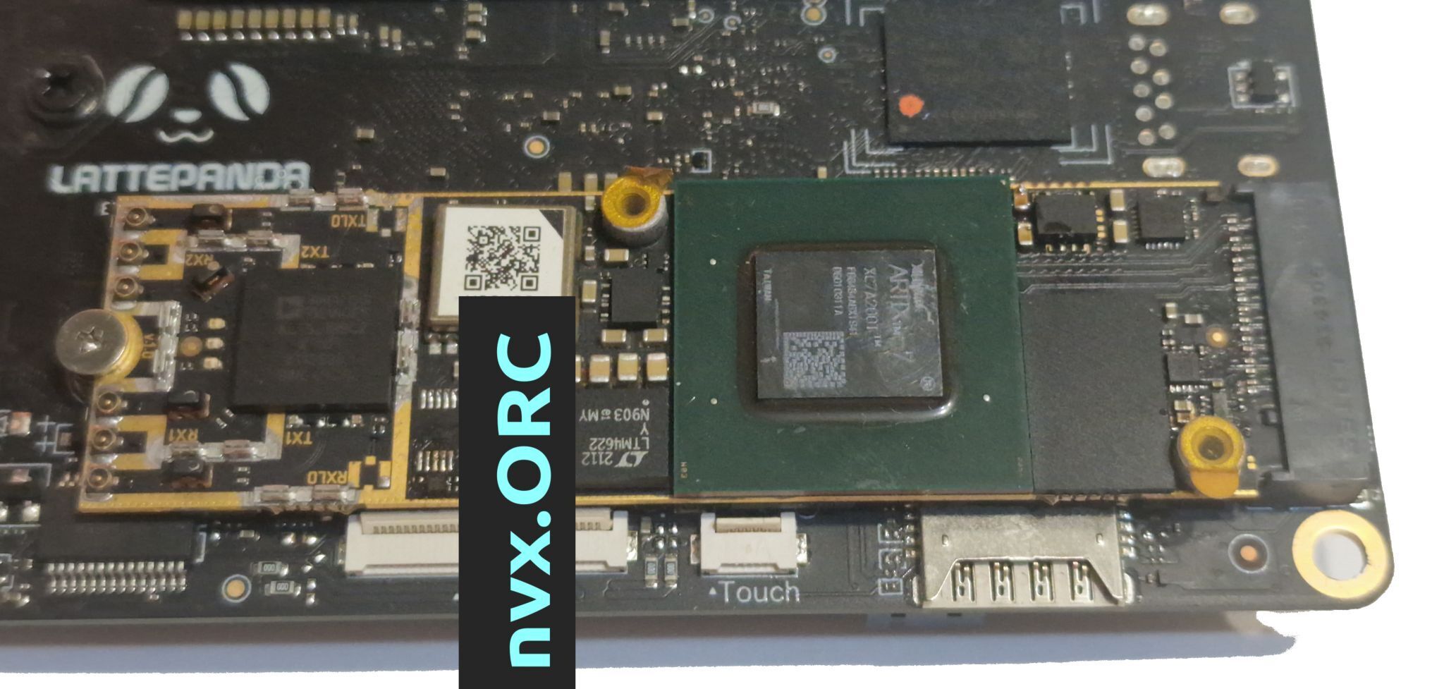
✅ Host system: Latte Panda Sigma
✅ Built-in UARTLite connected to a GPS SIM68 module
✅ High-speed data transfer via PCIe XDMA
✅ Two operation modes:
-
Linux TTY Driver interface (
/dev/ttyULx) -
Direct Python access via XDMA and
mmap
2. System Architecture
2.0 Board and Connections Overview
The project is based on a fully custom SDR board with PCIe interface:
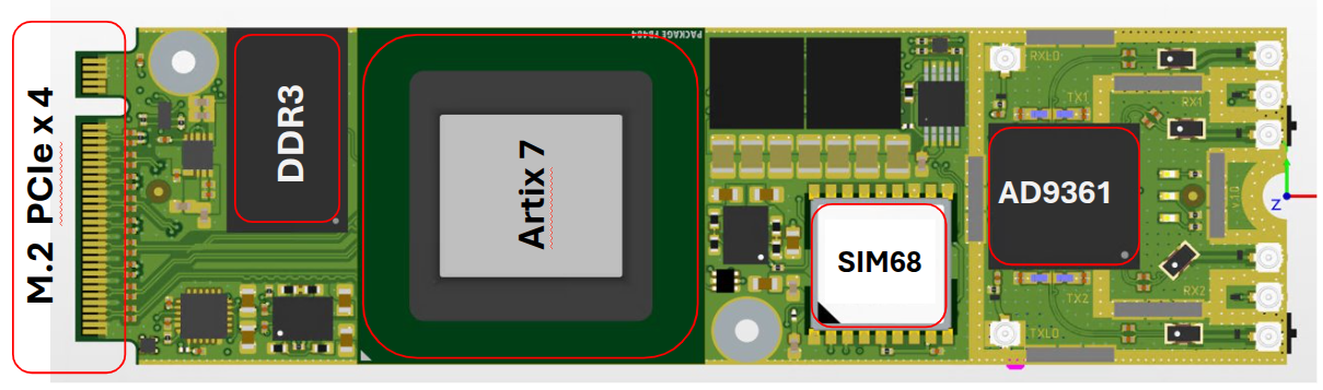
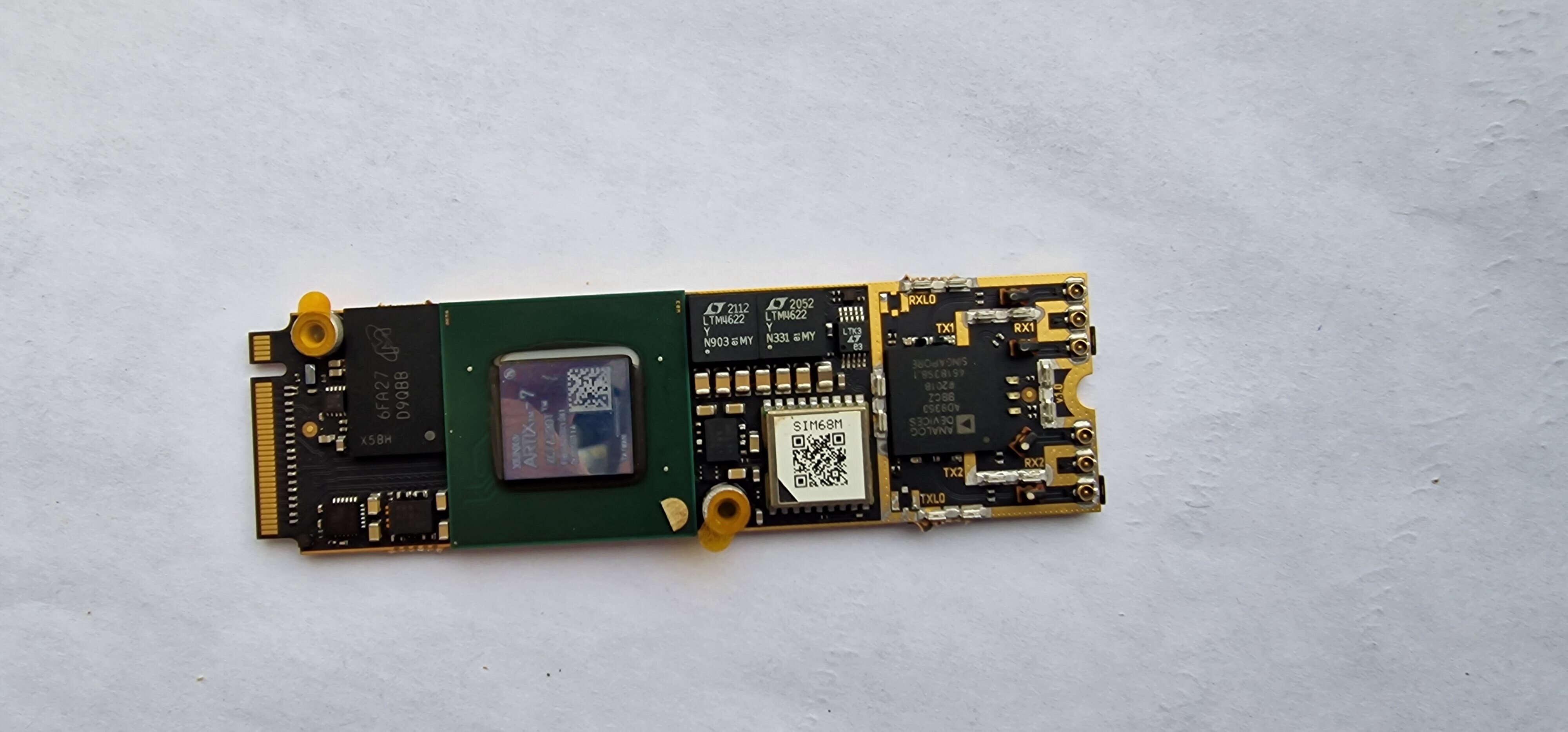
Main components:
| Component | Description |
|---|---|
| FPGA | Xilinx Artix-7 (XC7A200T) |
| RF Transceiver | Analog Devices AD9361 (70 MHz – 6 GHz) |
| GPS Module | SIM68 (NMEA 0183 Output) |
| DDR Memory | MT41K256M16HA-125 AAT |
| Host Board | LattePanda Sigma |
| Interface | PCIe Gen1 x4 (10 Gbps via M.2 connector) |
| Data Path | XDMA over AXI bus |
| UART Peripheral | AXI UARTLite IP Core (9600 baud) |
| Form Factor | M.2 2280 (80mm × 22mm) |
2.1 System Block Diagram
The diagram below illustrates the data flow chain between SIM68, UARTLite, XDMA, and the CPU:
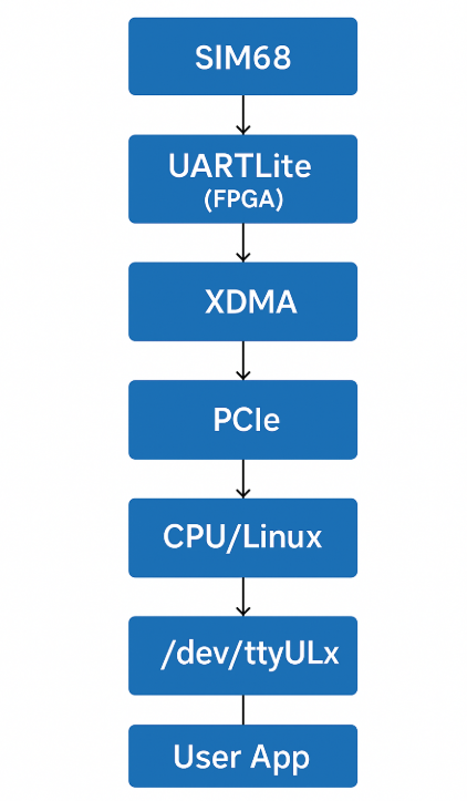
Data flow:
SIM68 transmits NMEA messages over UART to UARTLite inside FPGA.
UARTLite communicates with XDMA (PCIe DMA) via AXI bus.
XDMA sends the data through PCIe to the CPU (LattePanda Sigma).
CPU processes the data in user-space, communicating with the Linux kernel.
Linux Kernel exposes a TTY device or Python API (
/dev/ttyUL0).User Application interacts with the UART either via Python scripts or terminal.
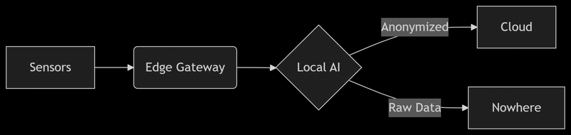
The second diagram shows direct Python access via XDMA without using the Linux driver:
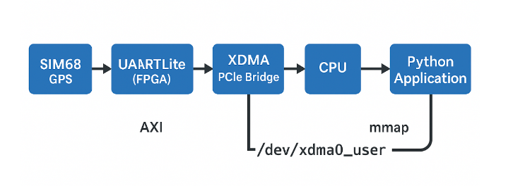
Data flow:
SIM68 transmits NMEA messages over UART to UARTLite inside FPGA.
UARTLite connects to XDMA over the AXI bus.
XDMA transfers data over PCIe to the CPU.
CPU maps
/dev/xdma0_userinto memory using mmap.Python Application directly accesses the UARTLite registers (RX FIFO / TX FIFO), bypassing the Linux kernel driver.
Thus, the interaction occurs without using the standard Linux TTY driver, which allows:
Minimizing system call overhead.
Reducing CPU load by utilizing async IO.
Rapidly prototyping and debugging FPGA-based systems.
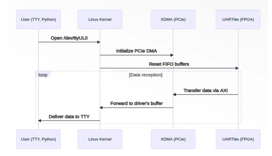
System Description
The system consists of the following components and their interconnections:
SIM68 (GPS Module)
- A GPS module that sends data over a UART interface.
- Connected to the UartLite (UART Controller) via UART.
UartLite (UART Controller)
- A UART controller that receives data from the GPS module.
- Connected to XDMA (PCIe DMA) via the AXI bus.
- AXI UARTLite Product Guide (PG142)
- AXI Interconnect Product Guide (PG059)
XDMA (PCIe DMA)
- A direct memory access (DMA) controller over PCIe.
- AXI PCIe DMA Product Guide (PG195)
- Connected to the CPU (Latte Panda Sigma) via PCIe.
CPU (Latte Panda Sigma)
- The central processor that processes data received from XDMA.
- Communicates with the Linux Kernel from the User-space.
Linux Kernel
- The operating system kernel running on the CPU.
- Provides interfaces for the User Application via TTY / Python.
- Linux TTY Documentation
User Application
- A user-space application that interacts with the Linux Kernel to access the data, either through TTY devices or Python scripts.
This architecture demonstrates how the driver manages communication with the UARTLite module.
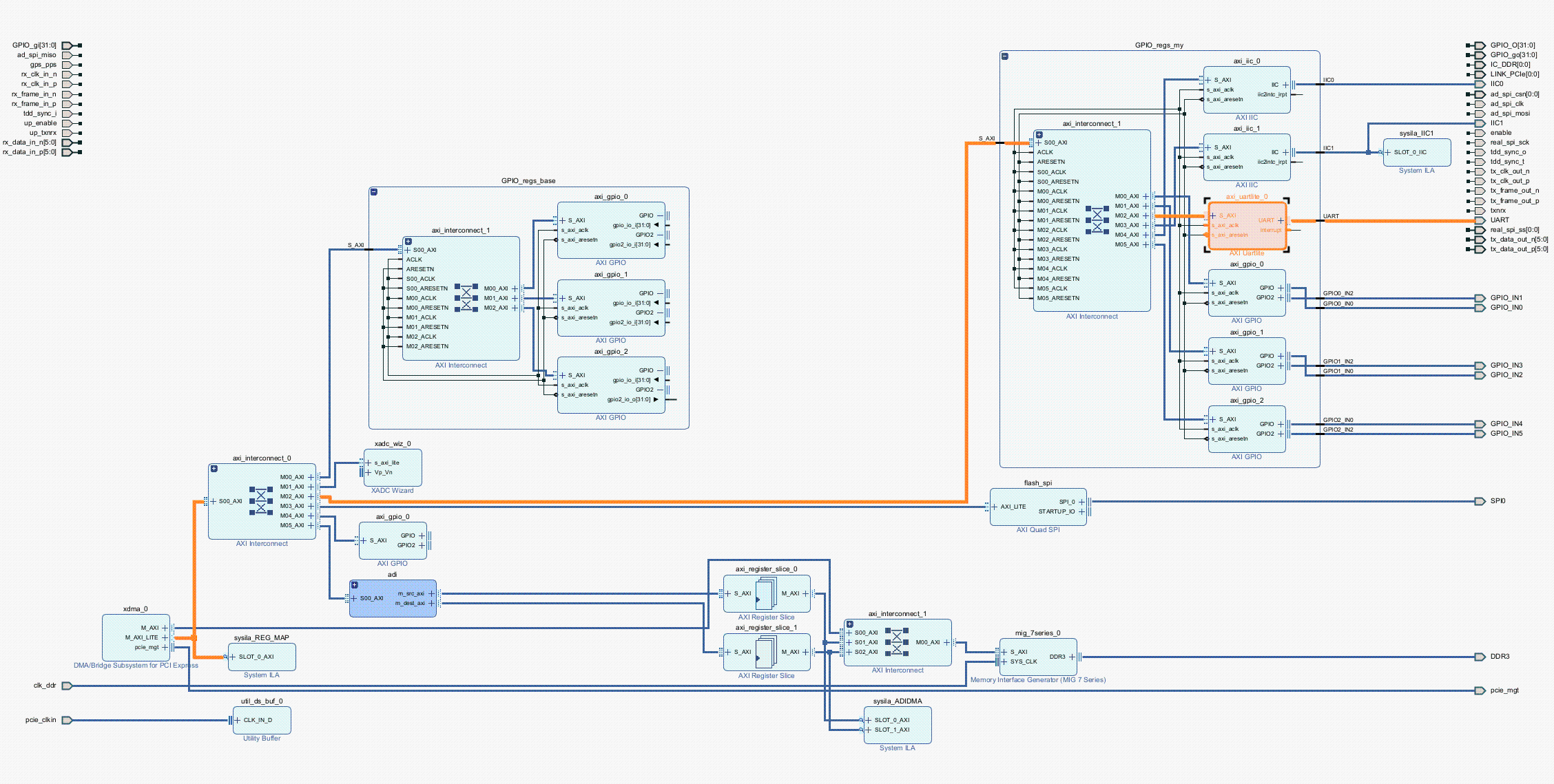
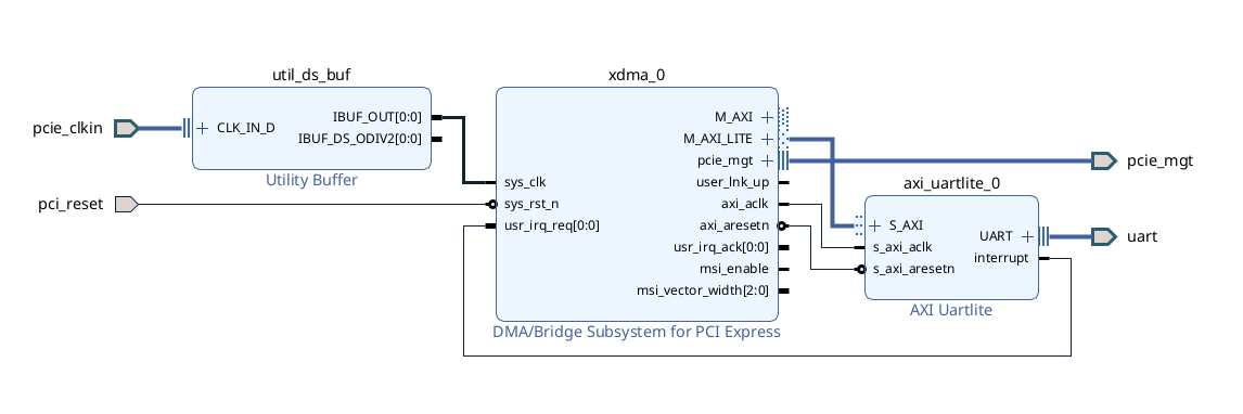
2.2 Vivado Block Diagram
The project uses XDMA (PCIe DMA Bridge).
AXI Interconnect connects XDMA, AXI Register Slice, and AXI UARTLite.
AXI UARTLite is mapped into the system via AXI Interconnect.
AXI GPIO blocks are also available for additional control.
Primary data path:
FPGA → AXI Interconnect → AXI UARTLite → XDMA → CPU/Linux
*
Below is a screenshot of the Vivado project:
or a simpler implementation focused only on UartLite:
2.3 XDMA and UartLite Configuration:
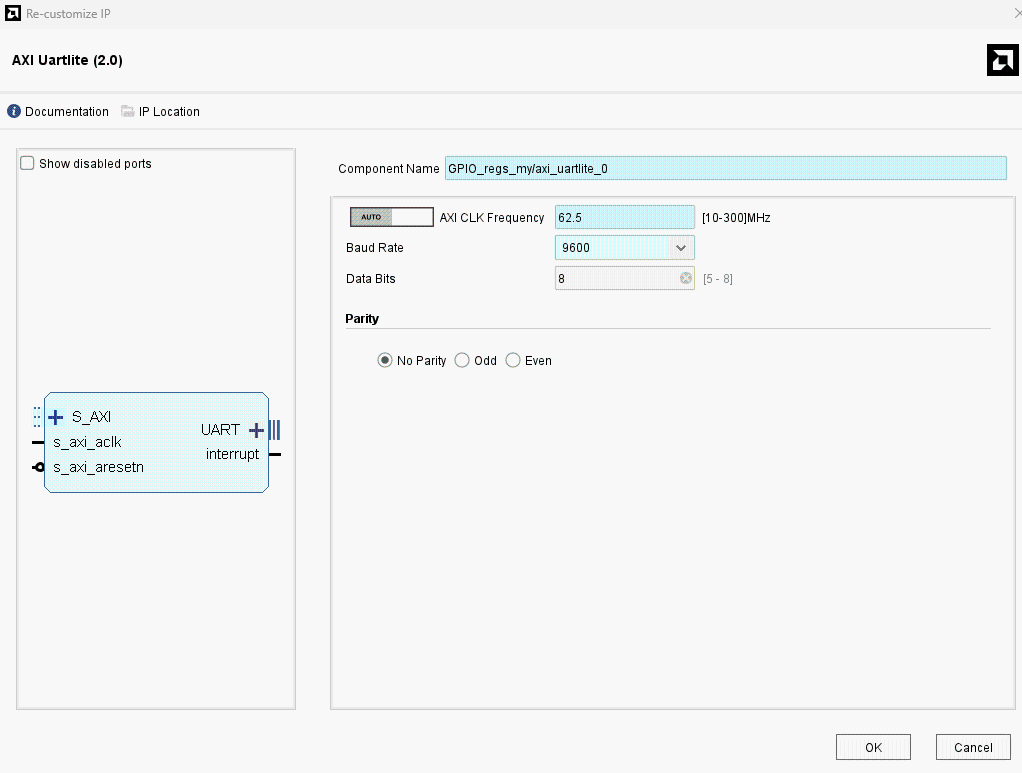
AXI UARTLite (IP Settings):
AXI Clock Frequency:
62.5 MHzUART Baud Rate:
9600 baudData Width:
8 bitsParity:
None (disabled)
(For higher speeds, 115200 baud can be configured.)
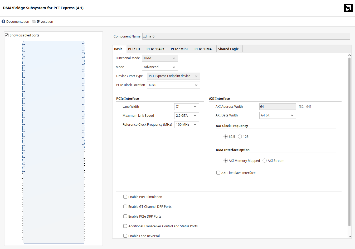
XDMA (PCIe DMA Settings):
AXI PCIe DMA Product Guide (PG195)


-
Channels:
- 1 H2C (Host-to-Card)
- 1 C2H (Card-to-Host)
Request IDs: 32 (read), 16 (write)
AXI ID Width: 4
Descriptor Bypass: Disabled
-
BAR (Base Address Register):
- 1MB AXI Lite space mapped at
0x00000000
- 1MB AXI Lite space mapped at
-
Interrupts:
- MSI enabled
- 16 interrupt vectors
-
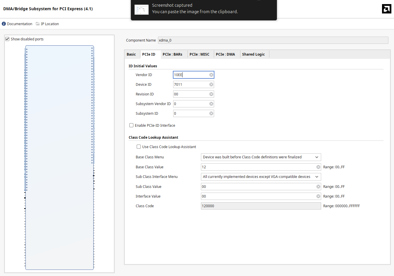
Device Identifiers (PCIe ID)
-
Vendor ID:
10EE(Xilinx) -
Device ID:
7011 -
Class Code:
120000
-
Vendor ID:
PCIe Configuration:
PCIe Base Specification (official summary)
PCIe Gen1 x1 (2.5 GT/s)
AXI Address Width: 64 bits
AXI Data Width: 64 bits
AXI Clock: 125 MHz
Режим: AXI Memory Mapped
UartLite Memory Mapping (Example Setup):

3. Driver Implementation
3.1 Setting Up the Environment
Hardware Platform:
SDR Board: Custom-built, FPGA Artix-7 200T
GPS Module: SIM68
Interfaces: PCIe, UART
Motherboard: LattePanda Sigma
Software Stack:
OS: Linux Kernel 6.x+
Tools: Vivado, Python, GCC
Debugging:
dmesg,minicom
3.2 Installing Dependencies
sudo apt-get update
sudo apt-get install -y build-essential dkms linux-headers-$(uname -r) git
sudo apt-get install -y pciutils lshw
sudo apt install -y gcc-13 g++-13
sudo apt install -y gpsd gpsd-clients
Packages explanation:
build-essential— GCC, Make, binutils (compiler toolchain)dkms— Dynamic Kernel Module Supportlinux-headers-$(uname -r)— Current kernel headersgit— Git version control systempciutils(lspci) — Inspect PCIe deviceslshw— Hardware information utilitygpsd,gpsd-clients— GPS Daemon and utilities
Check GCC version:
gcc-13 --version3.3 Hardware Check
Verify that the FPGA board is detected over PCIe:
lspci -d 10ee:Expected output:
59:00.0 Memory controller: Xilinx Corporation Device 70113.4 Driver Implementation
Driver Working Principle
When the module is loaded, the driver registers the PCIe device with Vendor ID 0x10EE and Device ID 0x7011.
It then creates a TTY device /dev/ttyUL0.
Incoming UARTLite data is processed via a workqueue and forwarded into the Linux TTY buffer (tty_flip_buffer_push), making it available for user-space applications.
Important Constants
#define DRIVER_NAME "uartlite_xdma"
#define VENDOR_ID 0x10EE  // Xilinx Vendor ID
#define DEVICE_ID 0x7011  // Device ID  for FPGA Hard PCIe block
#define UARTLITE_BASE_OFFSET 0x40000VENDOR_ID— Xilinx PCIe vendor IDDEVICE_ID— FPGA PCIe core device IDUARTLITE_BASE_OFFSET— UARTLite AXI address offset within XDMA space
UARTLite Register Offsets
(according to AXI UARTLite Product Guide PG142)
#define UARTLITE_RX_FIFO  0x00
#define UARTLITE_TX_FIFO  0x04
#define UARTLITE_STATUS   0x08
#define UARTLITE_CONTROL  0x0C
RX_FIFO: Read received bytes
TX_FIFO: Write bytes to transmit
STATUS: Check FIFO status
CONTROL: Control UARTLite behavior
Status Register Flags
#define STATUS_RXVALID    BIT(0) // 1 -  RX data available
#define STATUS_TXFULL     BIT(3) // 1 - TX FIFO full
Core Driver Structure
struct uartlite_priv {
    void __iomem *base;
    struct tty_port port;
    struct work_struct rx_work; // Обработчик RX (workqueue)
    bool running;
};base: Mapped address space (AXI base from XDMA)port: Linux TTY port structurerx_work: Workqueue for RX pollingrunning: Flag to control polling
UARTLite Access Functions
Check TX FIFO availability:
static int uartlite_tx_ready(struct uartlite_priv *priv)
{
    return !(ioread32(priv->base + UARTLITE_STATUS) & STATUS_TXFULL);
}
Write a byte to UARTLite:
static void uartlite_write_byte(struct uartlite_priv *priv, u8 val)
{
    iowrite32(val, priv->base + UARTLITE_TX_FIFO);
}
Check RX FIFO data availability:
static int uartlite_rx_ready(struct uartlite_priv *priv)
{
    return ioread32(priv->base + UARTLITE_STATUS) & STATUS_RXVALID;
}
Read a byte from RX FIFO:
static u8 uartlite_read_byte(struct uartlite_priv *priv)
{
    return ioread32(priv->base + UARTLITE_RX_FIFO);
}
RX Workqueue: Polling UARTLite
In this driver, RX FIFO polling (polling the UARTLite receive buffer) is used through a workqueue to simplify the implementation and avoid using interrupt-driven mechanisms.
Polling is a method of data handling where the CPU periodically checks the device's status and reads data if it is available.
How polling works in this driver:
1. The application opens the TTY device (/dev/ttyUL0)
The
uartlite_tty_open()function is called, which sets therunning = trueflag.The
uartlite_rx_work()handler is scheduled usingschedule_work().
2. The uartlite_rx_work() function checks if there is data in the RX FIFO
It reads the status register (
UARTLITE_STATUS).If there is data in the
RX FIFO(STATUS_RXVALID=1), it reads the data, buffers it, and pushes it into the TTY subsystem (tty_flip_buffer_push,tty_insert_flip_string).
3. If the FIFO is not empty, the data is passed to the TTY subsystem
- It calls:
-
tty_insert_flip_string(&priv->port, buf, count);
tty_flip_buffer_push(&priv->port);- The data then becomes available through
/dev/ttyUL0.
4. After processing the data, uartlite_rx_work() re-schedules itself
If
running = true, the function re-schedules itself (schedule_work()).If
running = false, the process stops (for example, when/dev/ttyUL0is closed).
static void uartlite_rx_work(struct work_struct *work)
{
  struct uartlite_priv *priv = container_of(work, struct uartlite_priv, rx_work);
    struct tty_struct *tty = tty_port_tty_get(&priv->port);
    unsigned char buf[16];
    int i, count;

    if (!tty)
        return;

    while (priv->running && uartlite_rx_ready(priv)) {
        count = 0;
        for (i = 0; i < sizeof(buf) && uartlite_rx_ready(priv); i++) {
            buf[i] = uartlite_read_byte(priv);
            count++;
        }
        if (count) {
            tty_insert_flip_string(&priv->port, buf, count);
            tty_flip_buffer_push(&priv->port);
        }
    }

    if (priv->running)
        schedule_work(&priv->rx_work);

    tty_kref_put(tty);
}
PCIe Device Registration
The PCIe driver is registered with the following structure:
static struct pci_driver uartlite_pci_driver = {
    .name = DRIVER_NAME,
    .id_table = uartlite_pci_tbl,
    .probe = uartlite_probe,
    .remove = uartlite_remove,
};
When the device is detected → the
uartlite_probe()function is called.When the device is removed → the
uartlite_remove()function is called.
The code below defines the PCI device ID table supported by the driver:
static const struct pci_device_id uartlite_pci_tbl[] = {
    { PCI_DEVICE(VENDOR_ID, DEVICE_ID) },
    { 0, }
};-
static const struct pci_device_id uartlite_pci_tbl[]- Defines the
uartlite_pci_tblarray, which lists the supported PCIe devices. - It is used by the Linux kernel to match devices that the driver can manage.
- Defines the
-
{ PCI_DEVICE(0x10EE, 0x7011) }-
PCI_DEVICE(vendor, device)— a macro that creates apci_device_idstructure. -
0x10EE— Vendor ID (Xilinx). -
0x7011— Device ID (corresponding to the UARTLite device in this case).
-
-
{ 0, }- A terminating element (zero identifier) that marks the end of the list.
If the system detects a device with Vendor ID 0x10EE and Device ID 0x7011, the driver’s probe() function will be called:
static int uartlite_probe(struct pci_dev *pdev, const struct pci_device_id *ent)The main tasks of uartlite_probe():
Allocate memory for the driver’s private structure (
uartlite_priv).Configure access to PCIe resources (I/O addresses, registers).
Register the UARTLite as a TTY device (
/dev/ttyUL0).Set up a workqueue for handling received data.
Module Initialization
module_init(uartlite_init);
module_exit(uartlite_exit);module_init(uartlite_init);— defines the function that will be called when the module is loaded into the Linux kernel.module_exit(uartlite_exit);— defines the function that will be called when the module is removed from the kernel.
These macros are the standard way in Linux kernel modules to specify the entry and exit points.
3.5 Full Driver Code (uartlite_xdma.c)
/*
 * UARTlite TTY Driver over XDMA
 *
 * Author:
 * Date:
 *
 * This driver enables communication with AXI UART Lite over PCIe XDMA.
 * It implements a TTY interface (ttyULx) for user-space interaction and supports
 * RX polling using a work queue mechanism.
 *
 * License: GPL v2
 */

 #include
#include
#include
#include
#include
#include  // tty_insert_flip_string и tty_flip_buffer_push
#include
#include  // work_struct

// External information
#define DRIVER_NAME "uartlite_xdma" // Driver name
#define VENDOR_ID 0x10EE  // Xilinx Vendor ID
#define DEVICE_ID 0x7011  // Device ID for 7-Series FPGA Hard PCIe block
#define UARTLITE_BASE_OFFSET 0x40000 // AXI base address

// AXI UART Lite Register Offsets
#define UARTLITE_RX_FIFO  0x00  // Receive FIFO
#define UARTLITE_TX_FIFO  0x04  // Transmit FIFO
#define UARTLITE_STATUS   0x08  // Status register
#define UARTLITE_CONTROL  0x0C  // Control register

// Status Register Flags
#define STATUS_RXVALID    BIT(0) // Data available in RX FIFO
#define STATUS_TXFULL     BIT(3) // TX FIFO is full


struct uartlite_priv {
    void __iomem *base;
    struct tty_port port;
    struct work_struct rx_work; // Polling
    bool running;
};

static struct tty_driver *uartlite_tty_driver;

/* UART Lite Functions */
static int uartlite_tx_ready(struct uartlite_priv *priv)
{
    return !(ioread32(priv->base + UARTLITE_STATUS) & STATUS_TXFULL);
}

static void uartlite_write_byte(struct uartlite_priv *priv, u8 val)
{
    iowrite32(val, priv->base + UARTLITE_TX_FIFO);
}

static int uartlite_rx_ready(struct uartlite_priv *priv)
{
    return ioread32(priv->base + UARTLITE_STATUS) & STATUS_RXVALID;
}

static u8 uartlite_read_byte(struct uartlite_priv *priv)
{
    return ioread32(priv->base + UARTLITE_RX_FIFO);
}

/* Work function for polling RX FIFO */
static void uartlite_rx_work(struct work_struct *work)
{
    struct uartlite_priv *priv = container_of(work, struct uartlite_priv, rx_work);
    struct tty_struct *tty = tty_port_tty_get(&priv->port);
    unsigned char buf[16];
    int i, count;

    if (!tty)
        return;

    while (priv->running && uartlite_rx_ready(priv)) {
        count = 0;
        for (i = 0; i < sizeof(buf) && uartlite_rx_ready(priv); i++) {
            buf[i] = uartlite_read_byte(priv);
            count++;
        }
        if (count) {
            tty_insert_flip_string(&priv->port, buf, count);
            tty_flip_buffer_push(&priv->port);
        }
    }

    if (priv->running)
        schedule_work(&priv->rx_work);

    tty_kref_put(tty);
}

/* TTY Operations */
static int uartlite_tty_open(struct tty_struct *tty, struct file *filp)
{
    struct uartlite_priv *priv = container_of(tty->port, struct uartlite_priv, port);
    priv->running = true;
    schedule_work(&priv->rx_work);
    return tty_port_open(tty->port, tty, filp);
}

static void uartlite_tty_close(struct tty_struct *tty, struct file *filp)
{
    struct uartlite_priv *priv = container_of(tty->port, struct uartlite_priv, port);
    priv->running = false;
    cancel_work_sync(&priv->rx_work);
    tty_port_close(tty->port, tty, filp);
}


#if LINUX_VERSION_CODE <= KERNEL_VERSION(6, 5, 0)
static int uartlite_tty_write(struct tty_struct *tty, const unsigned char *buf, int count)
#else
static ssize_t uartlite_tty_write(struct tty_struct *tty, const u8 *buf, size_t count)
#endif
{
    struct uartlite_priv *priv = tty->driver_data;
    int i;

    for (i = 0; i < count; i++) {
        while (!uartlite_tx_ready(priv))
            cpu_relax();
        uartlite_write_byte(priv, buf[i]);
    }
    return i;
}


static unsigned int uartlite_tty_write_room(struct tty_struct *tty)
{
    struct uartlite_priv *priv = tty->driver_data;
    return uartlite_tx_ready(priv) ? 16 : 0;
}

static unsigned int uartlite_tty_chars_in_buffer(struct tty_struct *tty)
{
    return 0;
}

static const struct tty_operations uartlite_tty_ops = {
    .open = uartlite_tty_open,
    .close = uartlite_tty_close,
    .write = uartlite_tty_write,
    .write_room = uartlite_tty_write_room,
    .chars_in_buffer = uartlite_tty_chars_in_buffer,
};

/* TTY Port Initialization */
static int uartlite_port_activate(struct tty_port *port, struct tty_struct *tty)
{
    struct uartlite_priv *priv = container_of(port, struct uartlite_priv, port);
    tty->driver_data = priv;
    return 0;
}

static void uartlite_port_shutdown(struct tty_port *port)
{
    struct uartlite_priv *priv = container_of(port, struct uartlite_priv, port);
    priv->running = false;
    cancel_work_sync(&priv->rx_work);
}

static const struct tty_port_operations uartlite_port_ops = {
    .activate = uartlite_port_activate,
    .shutdown = uartlite_port_shutdown,
};

/* PCI Probe Function */
static int uartlite_probe(struct pci_dev *pdev, const struct pci_device_id *ent)
{
    struct uartlite_priv *priv;
    int ret;

    priv = devm_kzalloc(&pdev->dev, sizeof(*priv), GFP_KERNEL);
    if (!priv)
        return -ENOMEM;

    ret = pcim_enable_device(pdev);
    if (ret)
        return ret;

    priv->base = pcim_iomap(pdev, 0, 0);
    if (!priv->base)
        return -ENOMEM;

    priv->base += UARTLITE_BASE_OFFSET;

    tty_port_init(&priv->port);
    priv->port.ops = &uartlite_port_ops;
    INIT_WORK(&priv->rx_work, uartlite_rx_work);
    priv->running = false;

    tty_port_register_device(&priv->port, uartlite_tty_driver, 0, &pdev->dev);

    pci_set_drvdata(pdev, priv);
    dev_info(&pdev->dev, "UARTlite over XDMA registered as TTY");
    return 0;
}

static void uartlite_remove(struct pci_dev *pdev)
{
    struct uartlite_priv *priv = pci_get_drvdata(pdev);
    tty_unregister_device(uartlite_tty_driver, 0);
    tty_port_destroy(&priv->port);
}

static const struct pci_device_id uartlite_pci_tbl[] = {
    { PCI_DEVICE(VENDOR_ID, DEVICE_ID) },
    { 0, }
};

static struct pci_driver uartlite_pci_driver = {


    .name = DRIVER_NAME,
    .id_table = uartlite_pci_tbl,
    .probe = uartlite_probe,
    .remove = uartlite_remove,
};

/* Module Initialization */
static int __init uartlite_init(void)
{
    int ret;

    uartlite_tty_driver = tty_alloc_driver(1, TTY_DRIVER_REAL_RAW | TTY_DRIVER_DYNAMIC_DEV);
    if (IS_ERR(uartlite_tty_driver))
        return PTR_ERR(uartlite_tty_driver);

    uartlite_tty_driver->driver_name = DRIVER_NAME;
    uartlite_tty_driver->name = "ttyUL";
    uartlite_tty_driver->major = 0;
    uartlite_tty_driver->minor_start = 0;
    uartlite_tty_driver->type = TTY_DRIVER_TYPE_SERIAL;
    uartlite_tty_driver->subtype = SERIAL_TYPE_NORMAL;
    uartlite_tty_driver->init_termios = tty_std_termios;
    uartlite_tty_driver->init_termios.c_cflag = B9600 | CS8 | CREAD | HUPCL | CLOCAL;

    tty_set_operations(uartlite_tty_driver, &uartlite_tty_ops);

    ret = tty_register_driver(uartlite_tty_driver);
    if (ret) {
        tty_driver_kref_put(uartlite_tty_driver);
        return ret;
    }

    ret = pci_register_driver(&uartlite_pci_driver);
    if (ret) {
        tty_unregister_driver(uartlite_tty_driver);
        tty_driver_kref_put(uartlite_tty_driver);
    }

    return ret;
}

static void __exit uartlite_exit(void)
{
    pci_unregister_driver(&uartlite_pci_driver);
    tty_unregister_driver(uartlite_tty_driver);
    tty_driver_kref_put(uartlite_tty_driver);
}

module_init(uartlite_init);
module_exit(uartlite_exit);

MODULE_LICENSE("GPL v2");
MODULE_AUTHOR("Konstantin");
MODULE_DESCRIPTION("UARTlite TTY driver over XDMA with RX support");
3.6 Building, Testing, and Debugging
Before building the driver, make sure that the Linux kernel headers are installed:
sudo apt update
sudo apt install -y linux-headers-$(uname -r)
To verify:
ls /lib/modules/$(uname -r)/buildIf the directory exists, the headers are installed correctly.
Building the Driver
Below is the Makefile used to build the driver:
# Build the kernel module
obj-m += uartlite_xdma.o
# Kernel build directory (default: current running kernel)
KDIR ?= /lib/modules/$(shell uname -r)/build
# Build the module
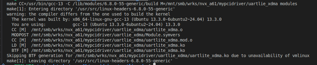
all:
make CC=/usr/bin/gcc-13 -C $(KDIR) M=$(PWD) modules
# Clean up compiled files
clean:
make -C $(KDIR) M=$(PWD) clean
# Install the module into the system
install:
make -C $(KDIR) M=$(PWD) modules_install
# Enable debugging symbols (-g flag for debugging)
EXTRA_CFLAGS += -g
# Define targets that are not actual files
.PHONY: all clean installRun the build command:
makeAfter a successful build, a file named uartlite_xdma.ko will appear — this is the ready-to-use kernel module.
Expected output:
To verify:
ls -l uartlite_xdma.koExpected output example:
-rwxr-xr-x 1 nvx root 390152 Mar 13 18:15 uartlite_xdma.koLoading the Driver
Load the driver into the kernel and verify that it is loaded:
sudo insmod uartlite_xdma.ko
lsmod | grep uartlite_xdma
If successful, it should appear in the module list:
uartlite_xdma 12288 0View driver logs:
sudo dmesg | tail -n 20Example output:

Check for the TTY device:
ls /dev/ttyUL*Example output:
/dev/ttyUL0Testing the Driver
To check the functionality:
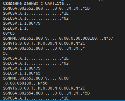
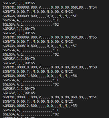
sudo minicom -D /dev/ttyUL0Expected NMEA output:
$GPGGA,123456.78,5540.1234,N,03734.5678,E,1,08,0.9,100.0,M,0.0,M,,*47Example output without a GPS antenna connected:
You can also connect the TTY device to gpsd:
Start gpsd and bind it to /dev/ttyUL0:
sudo gpsd /dev/ttyUL0 -F /var/run/gpsd.sock/dev/ttyUL0— the UART device connected to the GPS module-F /var/run/gpsd.sock— creates a UNIX socket for GPS applications
Or:
sudo gpsd -N -D3 -F /var/run/gpsd.sock /dev/ttyUL0-N— prevents gpsd from daemonizing (good for debugging)-D3— sets debug verbosity/dev/ttyUL0— UART device to use
Check if gpsd is running:
ps aux | grep gpsdExpected output:
root 7131 0.0 0.0 9084 2432 pts/3 S+ 18:51 0:00 grep --color=auto gpsdRun cgps to see live GPS data:
cgps -sExample output (when GPS is locked):
Time: 2025-03-13T12:34:56Z
Latitude: 55.7558 N
Longitude: 37.6173 E
Speed: 0.5 km/h
Altitude: 200 m
Check raw NMEA data from the GPS:
gpspipe -rExample output:
$GPGGA,123456.00,5537.348,N,03736.882,E,1,08,1.0,200.0,M,0.0,M,,*47
$GPRMC,123456.00,A,5537.348,N,03736.882,E,0.5,45.0,130324,,,A*7C
Unloading the Driver
To remove the module:
sudo rmmod uartlite_xdmaTo clean up the build files:
make clean5. Working with UARTLite via XDMA in Python
Besides using the Linux driver, you can work directly with UARTLite via XDMA using Python.
This approach is useful for debugging, quick testing, or safely implementing functionality in userspace.
5.1 Building the XDMA Driver
Before using XDMA, you need to compile and install the driver.
The XDMA driver is provided by Xilinx and supports working with PCIe devices implementing DMA.
👉 XDMA Linux Kernel Drivers GitHub
5.2 Cloning XDMA Driver Source Code
The driver sources are available in the official Xilinx repository:
git clone https://github.com/Xilinx/dma_ip_drivers.git
cd dma_ip_drivers/XDMA/linux-kernel###
5.3 Compiling the Driver
Before building, make sure you have the Linux kernel headers installed:
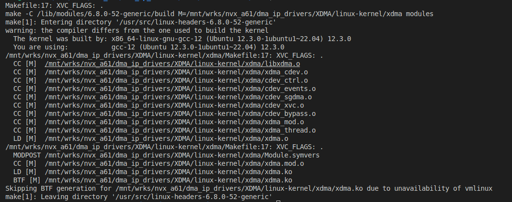
sudo apt-get install linux-headers-$(uname -r)Then compile the driver:
makeExample output:
5.4 Installing and Loading the Driver
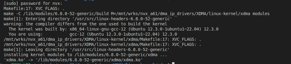
sudo make install
sudo modprobe xdma
Example output:
If this approach doesn't work, you can alternatively load the driver manually:
cd dma_ip_drivers/XDMA/linux-kernel/tests/
sudo ./load_driver.sh
Expected output:
interrupt_selection .
xdma                   24576  0
Loading driver...insmod xdma.ko interrupt_mode=2 ...

The Kernel module installed correctly and the xmda devices were recognized.
DONE
Verify that the module is loaded:
lsmod | grep xdmaExpected output:
xdma 110592 0After installing the driver, new device files should appear:
ls /dev/xdma*Expected output:
/dev/xdma0_c2h_0 /dev/xdma0_h2c_0 /dev/xdma0_control /dev/xdma0_userIf these files are present, the driver is successfully installed, and XDMA is ready to use.
Now you can proceed to testing UARTLite.
Example view on my setup:

| Device File | Description |
|---|---|
/dev/xdma0_c2h_0 |
C2H (Card-to-Host) — transfer data from FPGA to CPU |
/dev/xdma0_h2c_0 |
H2C (Host-to-Card) — transfer data from CPU to FPGA |
/dev/xdma0_user |
User control interface (for custom FPGA access) |
/dev/xdma0_xvc |
Xilinx Virtual Cable (XVC) — enables JTAG-over-PCIe (telnet localhost 2542 for testing) |
/dev/xdma0_control |
XDMA Control Register |
/dev/xdma0_events_0.../dev/xdma0_events_15
|
Event files for FPGA-to-CPU interrupt signaling |
The DMA driver is loaded and created the necessary
/dev/entries.You can read/write data through
c2h_0(FPGA → CPU) andh2c_0(CPU → FPGA).Interrupts can be monitored through
xdma_events_*.XVC allows working with JTAG over PCIe.
5.5 Python Code for UARTLite Access via XDMA (uaxdma.py)
Overview of the Python Code:
The script opens the /dev/xdma0_user device, mapping XDMA memory into the process address space using mmap.
It then accesses UARTLite registers at offset 0x40000, reading from RX FIFO and writing to TX FIFO.
This allows direct interaction with UARTLite without needing a kernel driver.
import os
import time
import numpy as np
import mmap
import asyncio

# ============================ #
#  XDMA + UARTLite (Unified)
# ============================ #
class XdmaUartLite:
    BASE_ADDR = 0x40000  ## Base address of UARTLite in XDMA

    # UARTLite Register Offsets
    RX_FIFO = 0x00
    TX_FIFO = 0x04
    STATUS = 0x08
    CONTROL = 0x0C

    # Флаги
    TX_FULL = 0x08
    RX_VALID = 0x01
    TX_RESET = 0x01
    RX_RESET = 0x02

    def __init__(self, device_index=0):
        """Initialize XDMA and UARTLite"""
        base = f"/dev/xdma{device_index}"

        # Open file for XDMA user space access
        self.fd_user = os.open(f"{base}_user", os.O_RDWR)

        # Create memory mapping for fast register access
        self.m_rmap = np.frombuffer(mmap.mmap(self.fd_user, int(1e6)), np.uint32)

        # Reset UARTLite FIFOs
        self.reset_fifos()

    def close(self):
        """Close XDMA file descriptors"""
        os.close(self.fd_user)


    # ============================ #
    #  XDMA Read/Write Access
    # ============================ #
    def read_reg(self, addr):
         """Read a 32-bit value from a register"""
        return self.m_rmap[addr >> 2] & 0xFFFF

    def write_reg(self, addr, data):
        """Write a 32-bit value to a register"""
        self.m_rmap[addr >> 2] = np.uint32(data)

    # ============================ #
    #  UARTLite Operations
    # ============================ #
    def reset_fifos(self):
        """Reset TX and RX FIFOs"""
        self.write_reg(self.BASE_ADDR + self.CONTROL, self.TX_RESET | self.RX_RESET)

    def send_byte(self, data):
        """Send a single byte via UARTLite"""
        while self.read_reg(self.BASE_ADDR + self.STATUS) & self.TX_FULL:
            pass  # Wait for TX FIFO to become available
        self.write_reg(self.BASE_ADDR + self.TX_FIFO, data)

    def recv_byte(self):
        """Receive a single byte via UARTLite"""
        while not (self.read_reg(self.BASE_ADDR + self.STATUS) & self.RX_VALID):
            pass  # Wait for data in RX FIFO
        return self.read_reg(self.BASE_ADDR + self.RX_FIFO)

    def send_data(self, data):
        """Send an array of bytes via UARTLite"""
        for byte in data:
            self.send_byte(byte)

    def recv_data(self, size):
        """Receive an array of bytes via UARTLite"""
        return bytearray([self.recv_byte() for _ in range(size)])

    async def recv_byte_async(self):
        """Asynchronously receive a single byte."""
        while not (self.read_reg(self.BASE_ADDR + self.STATUS) & self.RX_VALID):
            await asyncio.sleep(0.001)  # Дадим CPU отдохнуть, чтобы не нагружать 100%
        return self.read_reg(self.BASE_ADDR + self.RX_FIFO)

    async def recv_data_async(self, size):
        """Asynchronously receive an array of bytes."""
        return bytearray([await self.recv_byte_async() for _ in range(size)])

# ============================ #
#  Testing XDMA + UARTLite
# ============================ #

### Simple polling version
# if __name__ == "__main__":
#     xdma_uart = XdmaUartLite(device_index=0)
#     print("Waiting for data from UARTLite...")
#     while True:
#         data = xdma_uart.recv_data(128)
#         if data:
#             print(data.decode(errors="ignore").strip())

### Async version
async def main():
    uart = XdmaUartLite()
    while True:
        data = await uart.recv_data_async(128)
        print(data.decode(errors="ignore"))

asyncio.run(main())
To run it:
sudo python3 uaxdma.pyExample output:
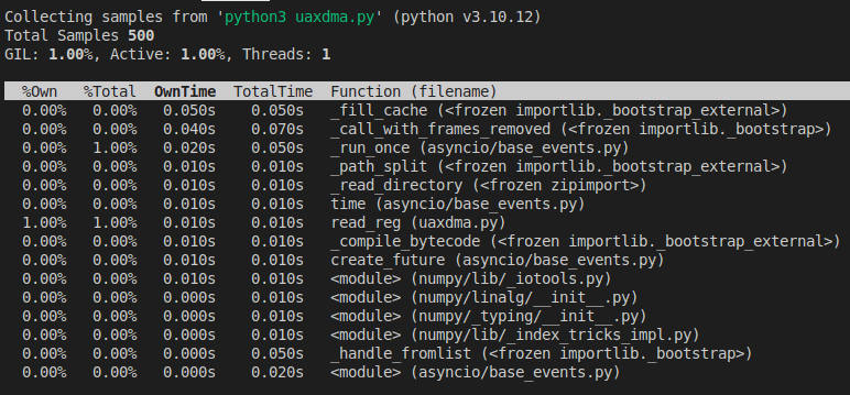
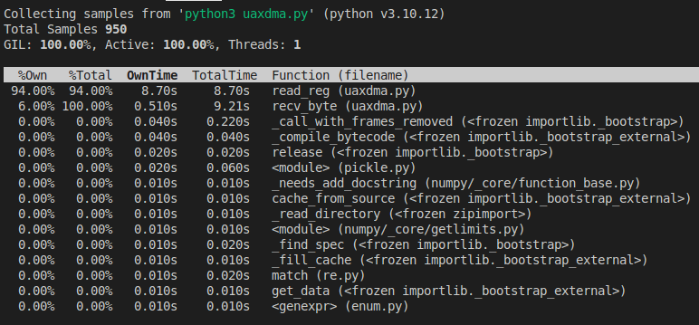
5.6 Performance Profiling
Performance analysis of uaxdma.py using py-spy for the async implementation:
without the async implementation:
CPU Load
Polling (second screenshot): 100% CPU usage, with
read_regconsuming 93% of the time.Async version (first screenshot): 1% CPU usage, with
read_reghaving almost no impact on the system.
Function Execution Time
Polling:
read_regtakes 8.7s out of 8.7s, meaning the program is almost entirely busy checking for data.Async:
read_regruns for only 0.01s, while most of the time is spent inasyncio.sleep(), significantly reducing CPU load.
Number of Calls
In the polling version,
recv_byteis called very frequently, heavily loading the CPU.In the async version,
recv_byteis called much less often because the code "waits" for data instead of constantly polling.
6. Conclusions
The developed solutions provide stable data transmission from the GPS module through UARTlite to the application, simplifying the integration of FPGA peripherals into SDR systems.
Using interrupts instead of polling can significantly reduce CPU load, while optimizing buffering can increase throughput.
This makes the solution suitable for a wide range of SDR projects, from prototyping to industrial applications.
This project implements two approaches for working with UARTlite via XDMA:
A classic Linux driver with a TTY interface, allowing the device to be used as a standard
UART.Direct access via Python, enabling application development without writing a kernel driver and allowing safer debugging compared to kernel-space development.
Advantages of the solution:
Support for standard Linux TTY devices.
Ability to work through Python without a custom driver.
Possible improvements:
- Add interrupt-based support instead of polling.
7. Conclusion
Developing a Linux driver and working with XDMA via Python enables efficient use of UARTlite and other IP cores in projects.
🚀 If you are interested in the topic of designing a custom SDR board (PCB development, SI/PI analysis, RF part analysis, etc.) and writing drivers, I'm ready to create a full series of articles on building an SDR device!