Differential clocks provide superior noise immunity and signal integrity compared to single-ended clocks, especially for high-frequency designs. Here's how to properly implement them in Xilinx FPGAs:
1. Hardware Connections
Supported Standards:
- LVDS (Low Voltage Differential Signaling)
- LVDS_25 (2.5V variant)
- LVPECL (via AC coupling)
- HSTL (High-Speed Transceiver Logic)
- Differential HSTL/SSTL for memory interfaces
Board-Level Connection Example:
FPGA Board:
DIFF_CLK_P  ----+
                |---- Xilinx FPGA MRCC/SRCC clock-capable pin pair
DIFF_CLK_N  ----+
2. Xilinx Clock Resources
Clock-Capable Pins:
- MRCC (Multi-Region Clock Capable)
- SRCC (Single-Region Clock Capable)
- HRCC (High-Range Clock Capable in UltraScale+)
Locating Pins:
- Consult your device's "SelectIO Resources" user guide
- In Vivado: Tools → Language Templates → HDL → Verilog/VHDL → IO → Differential Inputs
3. Implementation Methods
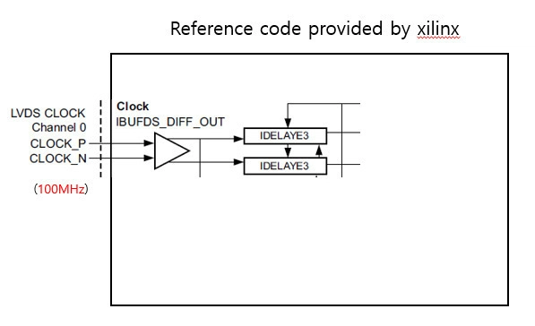
A. Using IBUFDS (Verilog)
verilog
// Differential input buffer for clocks
IBUFDS #(
    .DIFF_TERM("TRUE"),    // Enable differential termination
    .IBUF_LOW_PWR("FALSE") // High performance mode
) ibufds_inst (
    .I(clk_p),    // Differential positive input
    .IB(clk_n),   // Differential negative input
    .O(clk_out)   // Single-ended clock output
);
B. Using IBUFGDS for Global Clock Buffers
verilog
// For clock inputs that will drive global clock networks
IBUFGDS #(
    .DIFF_TERM("TRUE")
) ibufgds_inst (
    .I(sys_clk_p),
    .IB(sys_clk_n),
    .O(sys_clk)
);
C. VHDL Implementation
vhdl
library UNISIM;
use UNISIM.VCOMPONENTS.ALL;

entity clk_input is
port(
    clk_p : in std_logic;
    clk_n : in std_logic;
    clk_out : out std_logic
);
end entity;

architecture rtl of clk_input is
begin
    ibufds_inst : IBUFDS
    generic map (
        DIFF_TERM => TRUE,
        IBUF_LOW_PWR => FALSE
    )
    port map (
        I => clk_p,
        IB => clk_n,
        O => clk_out
    );
end architecture;
4. Constraints File (.xdc)
Pin Assignment:
set_property PACKAGE_PIN AD12 [get_ports clk_p]
set_property PACKAGE_PIN AD11 [get_ports clk_n]
set_property IOSTANDARD LVDS [get_ports {clk_p clk_n}]
Clock Definition:
create_clock -name sys_clk -period 5.000 [get_ports clk_p]5. UltraScale/UltraScale+ Specifics
For newer devices, use:
verilog
IBUFDS_GTE3 #(
    .REFCLK_EN_TX_PATH(1'b0),
    .REFCLK_HROW_CK_SEL(2'b00),
    .REFCLK_ICNTL_RX(2'b00)
) ibufds_gte3_inst (
    .I(clk_p),
    .IB(clk_n),
    .CEB(1'b0),
    .O(clk_out)
);
6. Best Practices
- Termination:
- Enable internal differential termination (DIFF_TERM="TRUE") when board doesn't have external termination
- Typical impedance: 100Ω between differential pairs
- PCB Layout:
- Keep trace lengths matched (±50ps)
- Route as differential pair with controlled impedance
- Minimize vias on clock traces
- Clock Management:
- Connect to MMCM/PLL for frequency synthesis
- Example MMCM connection:
verilog
MMCME2_BASE #(
    .CLKIN1_PERIOD(5.0),
    .CLKFBOUT_MULT_F(10),
    .CLKOUT0_DIVIDE_F(5)
) mmcm_inst (
    .CLKIN1(clk_out),
    .CLKOUT0(system_clk),
    // Other connections...
);- Simulation:
Simulate clock transitions with proper delays:
verilog
initial begin
    clk_p = 1'b0;
    clk_n = 1'b1;
    forever #2.5 begin
        clk_p = ~clk_p;
        clk_n = ~clk_n;
    end
end
7. Debugging Tips
- Clock Verification:
- Use ILA (Integrated Logic Analyzer) to verify clock integrity
- Check for duty cycle distortion
- Timing Constraints:
Set input delay constraints:
set_input_delay -clock [get_clocks sys_clk] -max 1.5 [get_ports clk_p]- Power Considerations:
- Monitor clock power consumption in Vivado Power Analysis
- Consider using BUFGCE for clock gating
Common Pitfalls to Avoid
- Incorrect Standard:
Using LVDS_25 when board provides 1.8V signals
- Missing Termination:
Forgetting to enable DIFF_TERM when needed
- Clock Domain Crossing:
Not properly synchronizing signals between differential clock domains
- Pin Mismatch:
Using non-clock-capable pins for high-speed differential clocks
By following these guidelines, you can reliably implement differential clock inputs in your Xilinx FPGA designs, ensuring optimal signal integrity and timing performance.