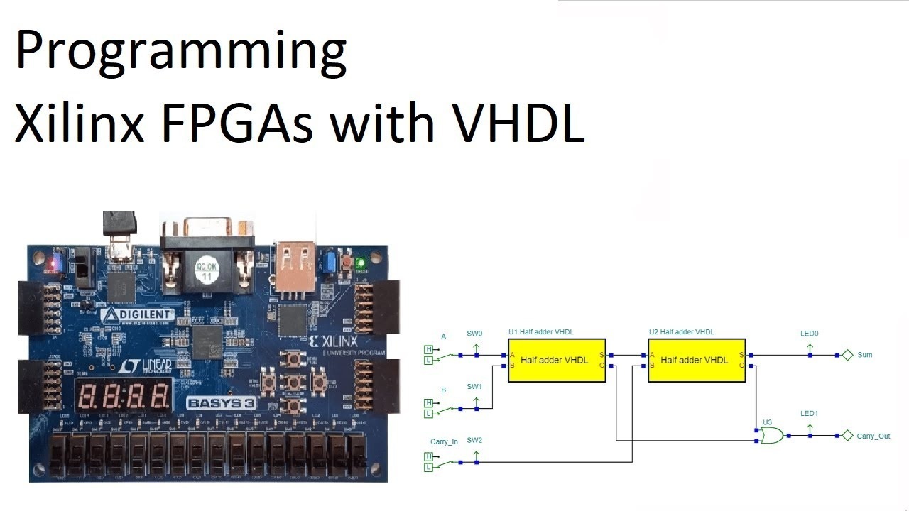
This guide covers the basics of programming Xilinx FPGAs using VHDL, including setup, coding, simulation, and synthesis.
🔧 1. Required Tools
Before starting, install these tools:
1.1 Xilinx Vivado (Free WebPACK Edition)
- Download from: Xilinx Downloads
- Supports Artix, Kintex, and Zynq FPGAs
- Includes VHDL simulator & synthesis tools
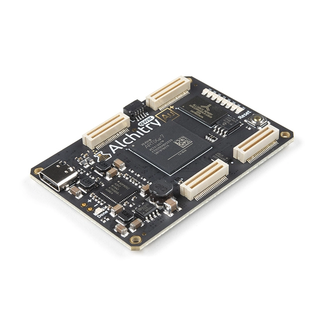
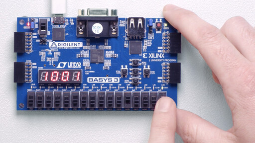
1.2 FPGA Development Board (Optional but Recommended)
Example boards:
📝 2. Creating a Simple VHDL Project
2.1 Open Vivado & Create a New Project
- Launch Vivado → Click "Create Project"
- Select RTL Project → Choose VHDL as the language.
- Select your FPGA board model (or manually pick the chip).
2.2 Write a Basic VHDL Example (Blinking LED)
📄 File: led_blink.vhd
vhdl
library IEEE;
use IEEE.STD_LOGIC_1164.ALL;
use IEEE.STD_LOGIC_UNSIGNED.ALL;

entity led_blink is
    Port (
        clk : in  STD_LOGIC;   -- 100MHz clock input
        led : out STD_LOGIC    -- LED output
    );
end led_blink;

architecture Behavioral of led_blink is
    signal counter : STD_LOGIC_VECTOR(26 downto 0) := (others => '0');
begin
    process(clk)
    begin
        if rising_edge(clk) then
            counter <= counter + 1;
        end if;
    end process;

    led <= counter(26);  -- Blink LED at ~1Hz (100MHz / 2^27)
end Behavioral;
2.3 Assign FPGA Pins (Constraints File)
📄 File: constraints.xdc
tcl
# Basys 3 Example
set_property PACKAGE_PIN W5 [get_ports clk]    # 100MHz Clock
set_property PACKAGE_PIN U16 [get_ports led]   # LED0
set_property IOSTANDARD LVCMOS33 [get_ports {led clk}]
⚙️ 3. Compile & Program the FPGA
3.1 Run Synthesis & Implementation
- Click "Run Synthesis" → Wait for completion.
- Click "Run Implementation" → Generates a bitstream.
3.2 Generate & Flash the Bitstream
- Click "Generate Bitstream".
- Connect your FPGA via USB-JTAG (Digilent/USB-Blaster).
- Click "Open Hardware Manager" → "Program Device".
✅ The LED should now blink at ~1Hz!
🔍 4. Simulating VHDL (Optional but Recommended)
Vivado includes a built-in simulator (XSim).
4.1 Create a Testbench
📄 File: tb_led_blink.vhd
vhdl
library IEEE;
use IEEE.STD_LOGIC_1164.ALL;

entity tb_led_blink is
end tb_led_blink;

architecture Behavioral of tb_led_blink is
    signal clk : STD_LOGIC := '0';
    signal led : STD_LOGIC;
begin
    -- Instantiate the design
    DUT: entity work.led_blink
    port map (
        clk => clk,
        led => led
    );

    -- Generate a 100MHz clock
    clk <= not clk after 5 ns;  -- 10ns period = 100MHz

    -- Stop simulation after 1ms
    process
    begin
        wait for 1 ms;
        std.env.stop;
    end process;
end Behavioral;
4.2 Run Simulation
- Right-click "Simulation Sources" → "Add Sources" → Select testbench.
- Click "Run Simulation" → "Run Behavioral Simulation".
- View waveforms in XSim.
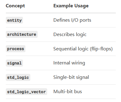
📌 5. Key VHDL Concepts for FPGAs
🚀 6. Next Steps
- Try UART communication (send/receive serial data).
- Learn Finite State Machines (FSMs) for complex logic.
- Explore Xilinx IP Integrator for pre-built modules (PLLs, RAM, etc.).